
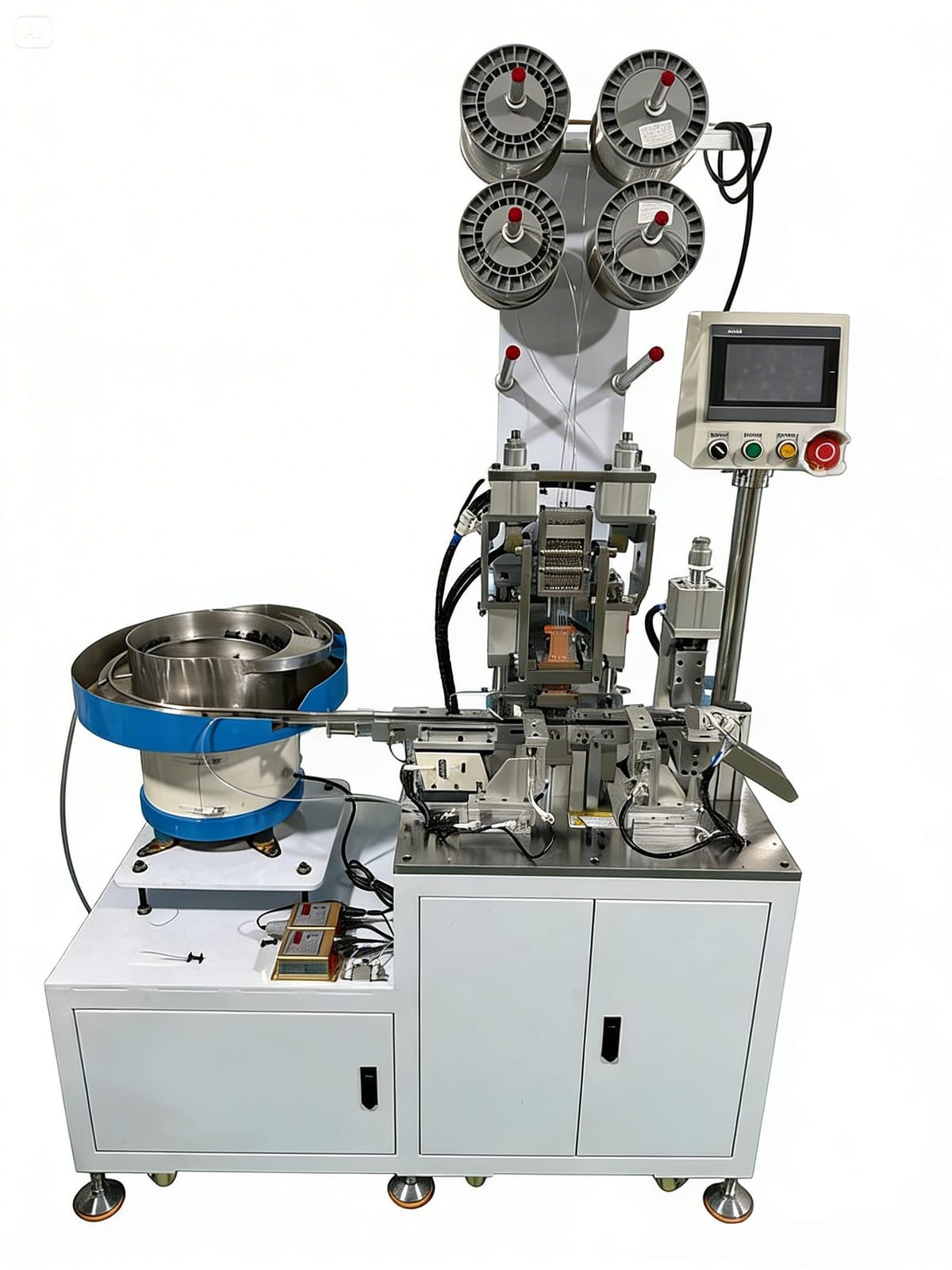
A bowl feeder sorts while it transports
A vibratory bowl feeder moves loose parts along an inclined circular track. Tooling on the track allows correctly oriented components to continue and returns or rejects the rest. An outfeed track then presents a controlled queue to the machine.
Reliable feeding depends on more than vibration speed. Bowl shape, track width, tooling features, surface coating, part level and downstream demand all influence flow. Sensors normally stop and restart feeding so the outfeed remains supplied without excessive pressure on queued parts.
Good candidates have a detectable stable orientation
Parts feed well when their geometry gives the tooling clear ways to distinguish correct and incorrect positions. Rigid components with repeatable dimensions and surfaces are easier to control than flexible, sticky or easily damaged items.
Provide samples from multiple lots because small changes in moulding flash, plating, oil or magnetism can alter behaviour. The feeder should be proven with the normal production range, including parts near dimensional limits, not only a small group selected for the trial.
- Distinct features for orientation
- Low tendency to nest or tangle
- Surface robust enough for controlled contact
- Consistent geometry across suppliers and lots
Know the warning signs of a poor feeding candidate
Flexible leads can intertwine, flat pieces can overlap, soft surfaces can mark and nearly symmetrical parts can defeat orientation checks. Components with oil, static charge or strong magnetic attraction may behave differently across the shift. These conditions do not always make bowl feeding impossible, but they increase development and control effort.
Alternative presentation may be better: trays, tubes, magazines, pallets, step feeders or manual loading into a mistake-proof nest. The right objective is stable part delivery to the process, not forcing every product into a bowl.
Run a feeder trial that reflects production
Measure sustained correctly oriented output, part damage, jam frequency, replenishment and recovery. Test starts from empty and overfilled conditions, normal pauses and the expected range of part lots. Confirm that downstream sensors prevent starvation without creating back-pressure.
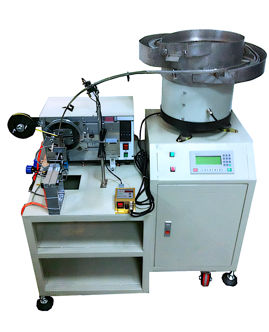
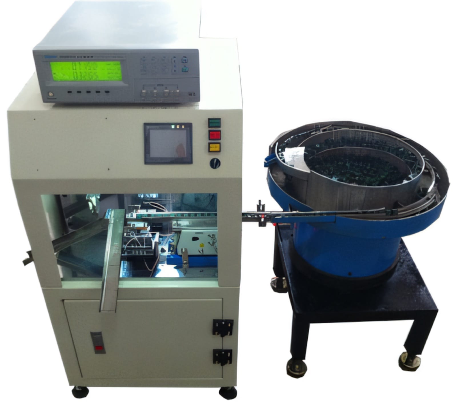
Several PME insertion, taping, soldering and testing machines can be configured with bowl feeding. The feeder and process tooling should be developed together so the orientation delivered by the bowl is the orientation the machine actually needs.
Relevant machinery for this process
Explore PME equipment that can support the operations discussed in this guide. Final machine selection should be confirmed against your component, materials and target output.
Plan the next step
Discuss your component and production target with PME.
Share a drawing, sample, current process and expected output. We can help map the right machines and level of integration.