
Treat the bobbin as part of the production system
A coil bobbin is not only an electrical and mechanical component. In automated production it is also a workpiece that must be fed, located, clamped, rotated, wound and transferred. Small features that cause no difficulty during manual assembly can become the main source of stops when a machine must recognise the part the same way every cycle.
Begin the bobbin review alongside the winding process. Record the wire range, number of windings, terminal method, tape or insulation operations and every surface used by tooling. At PM Electronics, we recommend reviewing real moulded samples as well as the drawing because flash, warpage, pin movement and supplier variation often determine whether a concept is production-ready.
- Winding window and flange geometry
- Terminal position and pin retention
- Surfaces available for locating and clamping
- Features that establish orientation
Define a usable winding window and wire path
The usable winding window is usually smaller than the space shown on a component drawing. Tool clearance, wire-guide approach, lead routing, traverse reversal and normal moulding radii all reduce the area available for controlled winding. If the guide cannot reach the flange cleanly, the process may create loose edges, crossovers or inconsistent layer build.
Provide a clear path for the start and finish leads. Slots, hooks and terminal positions should hold the wire without creating a sharp edge or an excessive bend. The design should also allow the machine to complete cutting, wrapping or termination without pulling finished turns away from the winding pack.
Make pins and terminals repeatable
Pin position influences more than the insertion operation. Winding nozzles, soldering fixtures and electrical-test probes may all reference the same terminals. Control insertion depth, straightness, orientation and retention force so the bobbin remains usable throughout the complete process.
Where pins are inserted automatically, give the tooling a stable support surface behind the insertion point and enough clearance around the pin location. Avoid near-symmetrical arrangements that allow an incorrectly oriented bobbin to enter the station. A simple physical difference between left and right can provide more dependable error prevention than an operator instruction.
- Consistent pin shoulder or insertion stop
- Tool access without interference from flanges
- Adequate material support around the pin
- A feature that prevents reversed loading
Design clear datums for feeding and fixturing
Automated machinery needs a small number of repeatable surfaces to establish position. Choose moulded datums that are stable, accessible and functionally related to the winding axis. Decorative faces, flexible walls and flash-prone edges are poor references because their position can change from part to part.
For bowl feeding or other bulk presentation, review how the bobbins nest, tangle and travel along a track. Parts that lock together may need a different feeding method or a packaging change. For pallet or manual loading, the nest should support the part without hiding the features needed by the winding, inspection or unloading tools.
Validate the full production tolerance
A machine trial should include bobbins from different cavities, moulding dates and approved suppliers. Test the smallest and largest acceptable dimensions, not only selected samples that sit near the nominal drawing. Run the intended wire, pins and insulation materials because their combined tolerances affect the final winding pack and terminal presentation.
Freeze the bobbin design only after pin insertion, winding, termination, taping, soldering and testing have been considered together. PME can evaluate component samples against standalone winding equipment or a connected production route so tooling decisions support stable output instead of moving a problem to the next station.
Relevant machinery for this process
Explore PME equipment that can support the operations discussed in this guide. Final machine selection should be confirmed against your component, materials and target output.
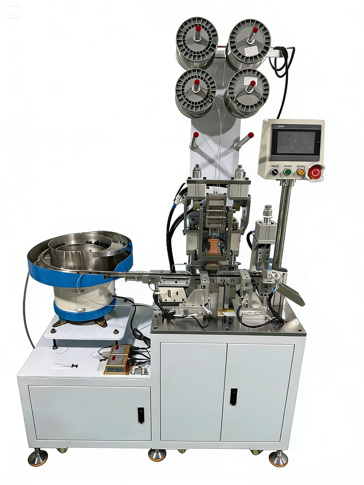 PME AUTOMATION
Pin Inserting Machine with Bowl Feeder
View machine ↗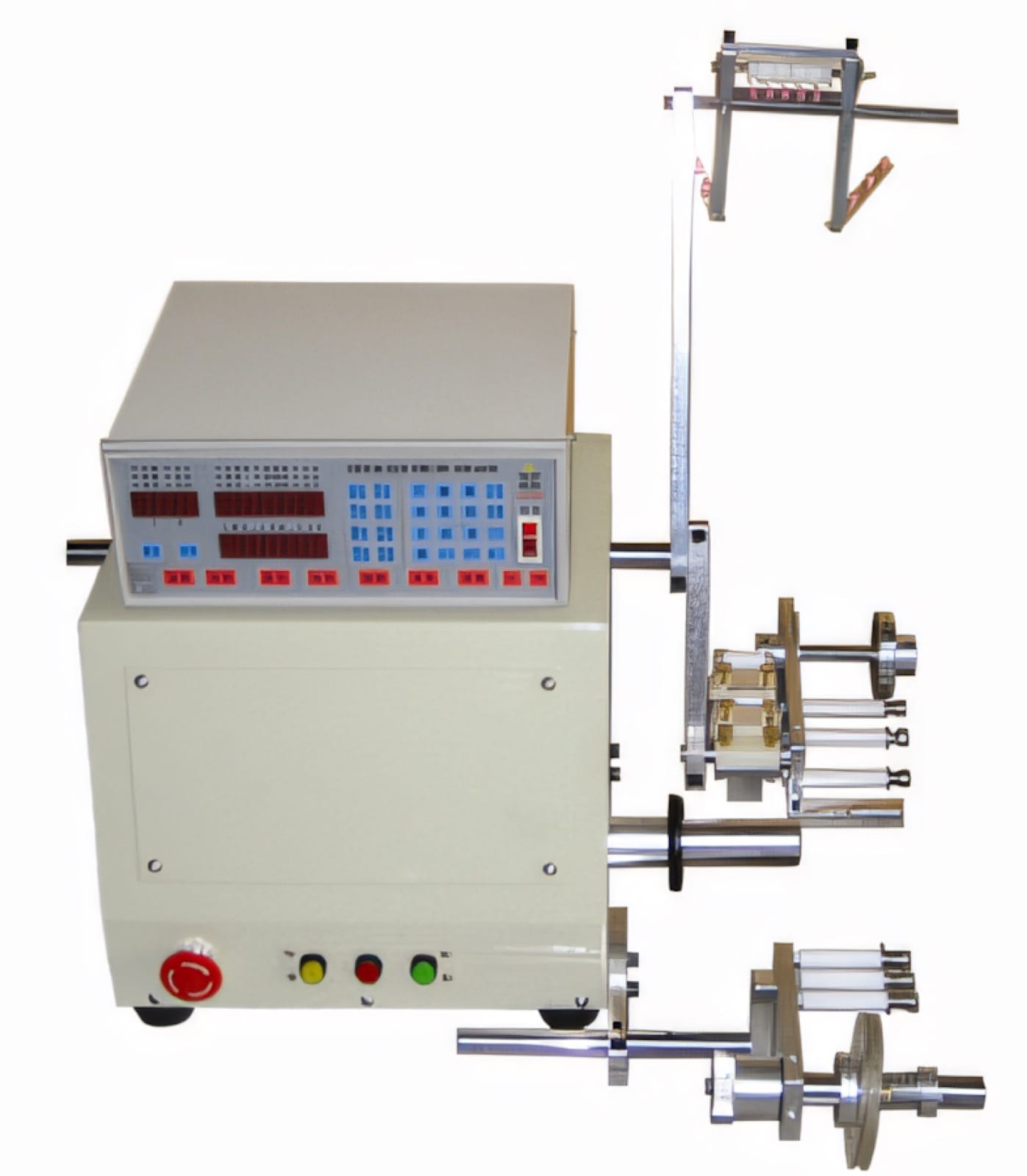 PME AUTOMATION
CNC Auto Winding Machine — 1 Spindle
View machine ↗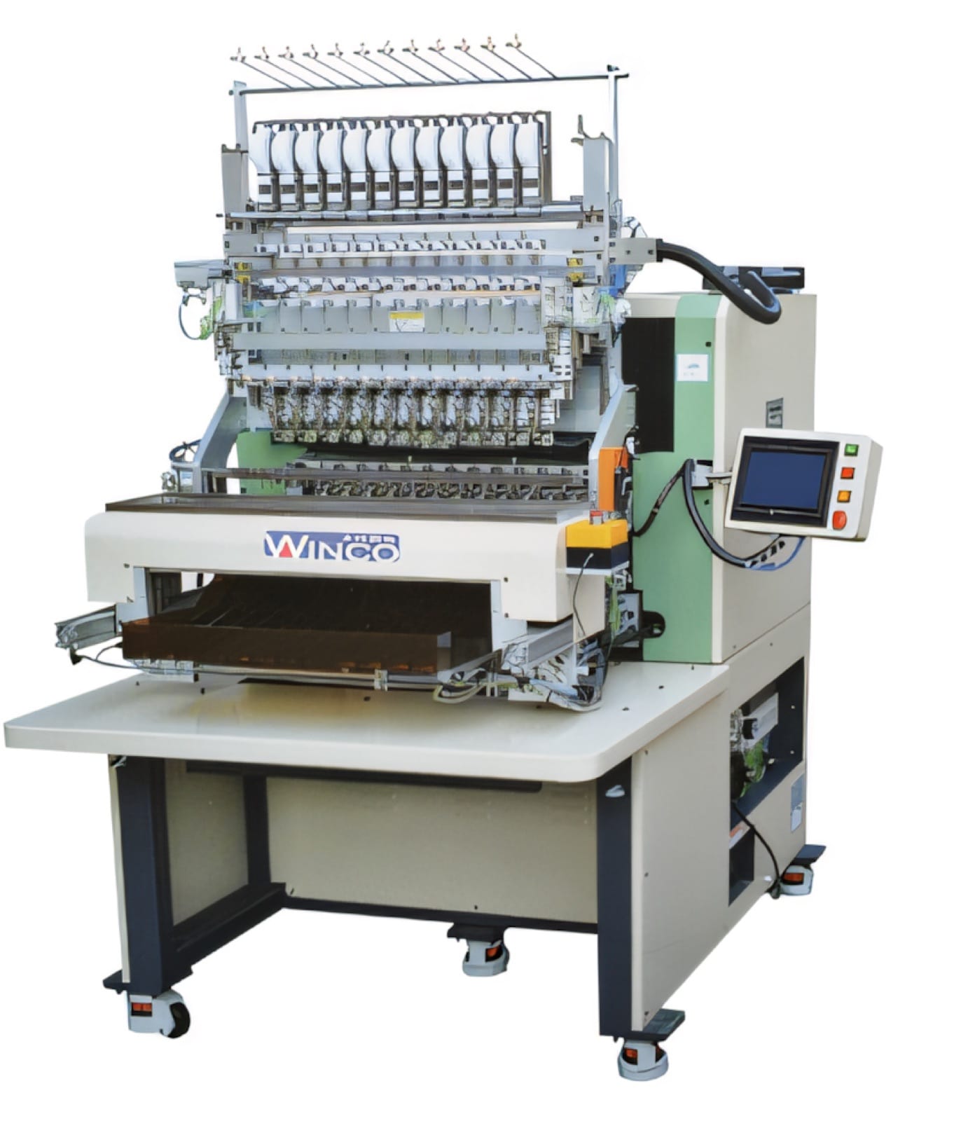 PME AUTOMATION
8/12/16/20 Spindles Auto Axis Winding Machine
View machine ↗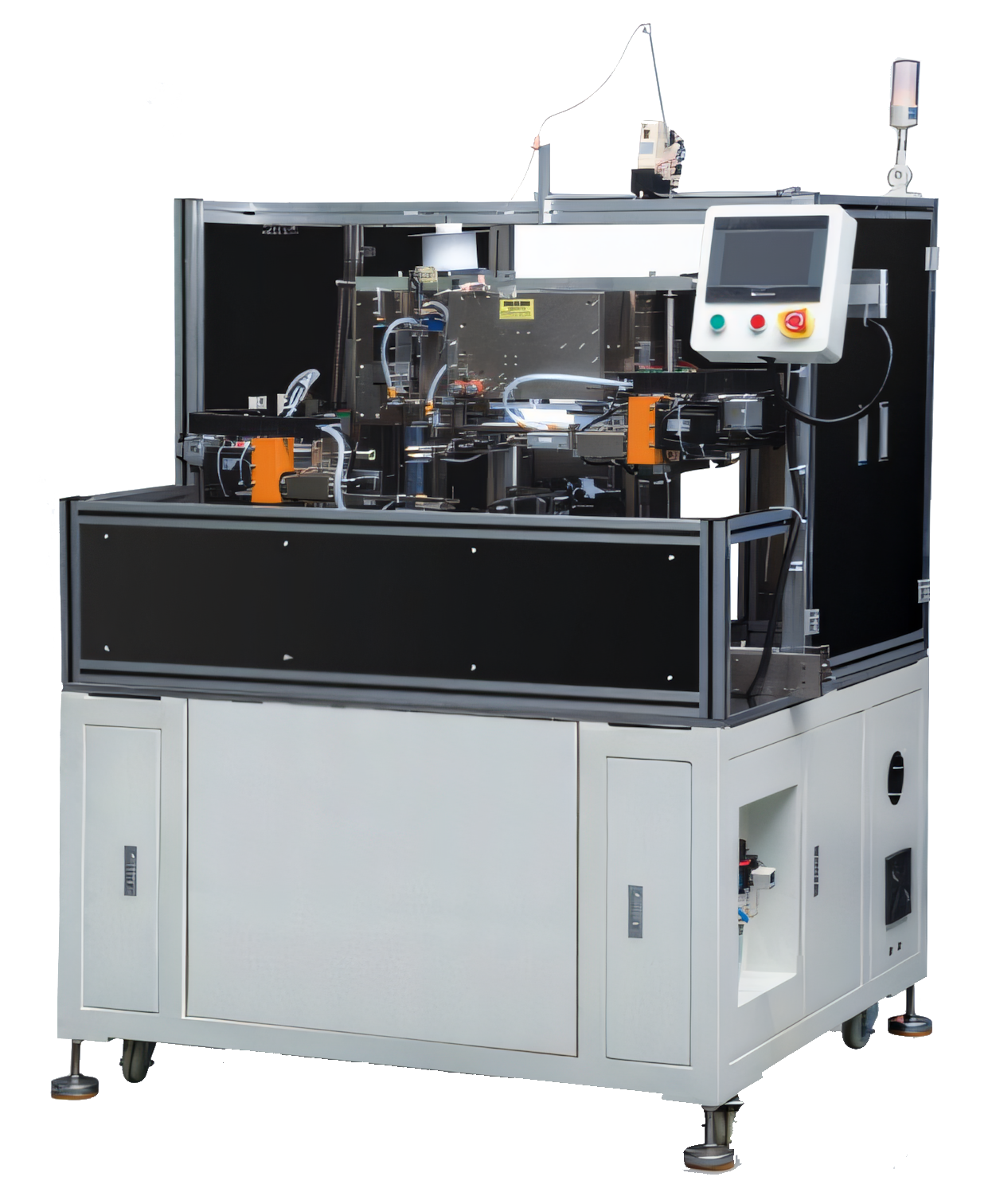 PME AUTOMATION
Auto Tube Insert, Winding & Taping Machine
View machine ↗Plan the next step
Discuss your component and production target with PME.
Share a drawing, sample, current process and expected output. We can help map the right machines and level of integration.