
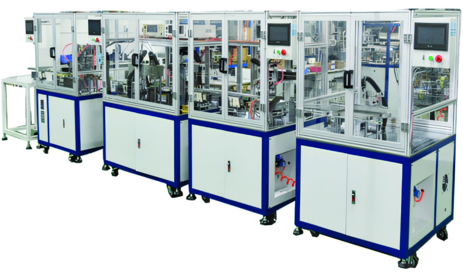
Build the route around the transformer design
The transformer manufacturing process begins with the component drawing, not a standard machine list. Bobbin size, wire range, turn count, insulation system, core construction, termination method and electrical limits determine the operations that are required. A small high-frequency transformer may follow a different route from a larger power component even when both use wound coils.
Create a process sheet for every product family and identify which features change between variants. This gives an automation supplier the information needed to design tooling, recipes and changeovers without overcommitting to a dedicated line too early.
- Bobbin, terminal and core geometry
- Primary and secondary winding sequence
- Tape type, width, overlap and insulation requirements
- Soldering method and production test limits
Select the core transformer manufacturing equipment
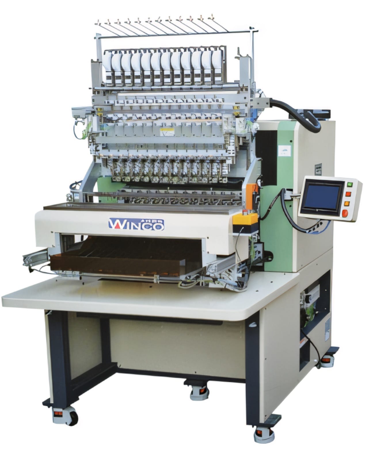
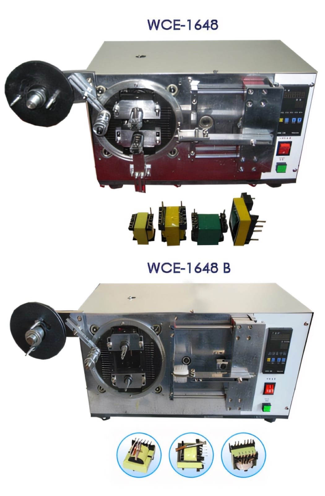
Most routes need bobbin or pin preparation, a transformer coil winding machine, insulation taping, termination or dip soldering, core assembly and electrical testing. Wire cutting, stripping, impregnation and curing may also be required. Each operation can be purchased as a standalone machine or combined into transformer manufacturing automation.
A multi-spindle winding machine supports stable, repeated products, while a single-spindle CNC machine can be more practical for varied work. The correct architecture is the one that meets good-parts output after loading, changeover and routine recovery are included.
Connect the stages without losing process control
An automatic transformer production line must control the interfaces between winding, taping, soldering and testing. The part needs a repeatable datum, protected wire presentation and a pass/fail status that follows it through the line. Common recipes should select the correct winding program, tape parameters and electrical limits together.
Where products vary frequently, modular stations with controlled transfer may provide a better migration path. Standardized nests and communication signals allow proven machines to be connected later without redesigning the complete process.
Validate output, quality and support
Acceptance should use representative bobbins, wire, tape, solder and cores. Measure sustained output, first-pass yield, winding appearance, tape coverage, solder quality, test repeatability, replenishment and changeover. Include planned faults so operators can demonstrate safe recovery.
PM Electronics can help map individual PME winding, taping and testing machines into a transformer production plan, including installation, commissioning, training and service support in India. The proposal should be based on samples, drawings and measurable acceptance criteria.
Relevant machinery for this process
Explore PME equipment that can support the operations discussed in this guide. Final machine selection should be confirmed against your component, materials and target output.
Plan the next step
Discuss your component and production target with PME.
Share a drawing, sample, current process and expected output. We can help map the right machines and level of integration.