
Understand what each test is intended to reveal
Hi-pot, or dielectric-strength testing, applies a controlled high-voltage condition to evaluate whether insulation can withstand the specified electrical stress without breakdown. Insulation-resistance testing measures how effectively the insulation limits leakage under its defined test condition. The two results are related to insulation quality, but they are not interchangeable.
Production limits, voltage, waveform, ramp, dwell and connection method must come from the approved product specification and applicable safety standard. They should be set by qualified engineering personnel. A machine supplier can implement the method, but should not invent product-safety limits from a similar-looking transformer or coil.
- Approved test points and connection sequence
- Required voltage, ramp, dwell and trip behaviour
- Insulation-resistance measurement conditions
- Rules for discharge, retest and rejected parts
Design fixtures for stable contact and adequate spacing
Test fixtures must contact the correct terminals without damaging them or exposing the operator to an energized point. Probe spacing, insulation material, surface cleanliness and routing should suit the maximum test condition. Sharp contamination paths and worn insulation can create fixture leakage that looks like a product failure.
Use positive part location and confirm presence before the test begins. If a product has several windings, cores or shields, the fixture and switching sequence should make the intended connections automatically and prevent the wrong recipe from energizing an incompatible arrangement.
Make operator safety part of the machine cycle
High-voltage production testing requires guarding, safety interlocks and a controlled sequence that prevents access during the test. The system should not rely on an operator remembering to keep clear. An interrupted cycle must remove energy safely, and the part should be discharged before access or transfer is allowed.
Risk assessment, electrical design and validation should be completed by competent people for the installation and local requirements. Clear indicators, fault messages and work instructions help operators understand whether a cycle passed, failed or stopped before a valid test was completed.
- Interlocked enclosure or guarded test zone
- Verified discharge before access
- Clear distinction between fail and incomplete test
- Controlled maintenance and calibration access
Validate measurement integrity and retest rules
Compare the production tester with an approved reference using good, marginal and known-failed samples. Study fixture leakage, contact repeatability and the effect of humidity, contamination and temperature where relevant. A regular verification routine should detect probe or fixture deterioration before it changes production decisions.
Define retest policy before launch. Repeated high-voltage exposure may be restricted by the product specification, and an operator should not be able to pass a failed unit by testing it until a favourable result appears. Record the original result, authorized disposition and final status.
Integrate high-voltage tests without losing traceability
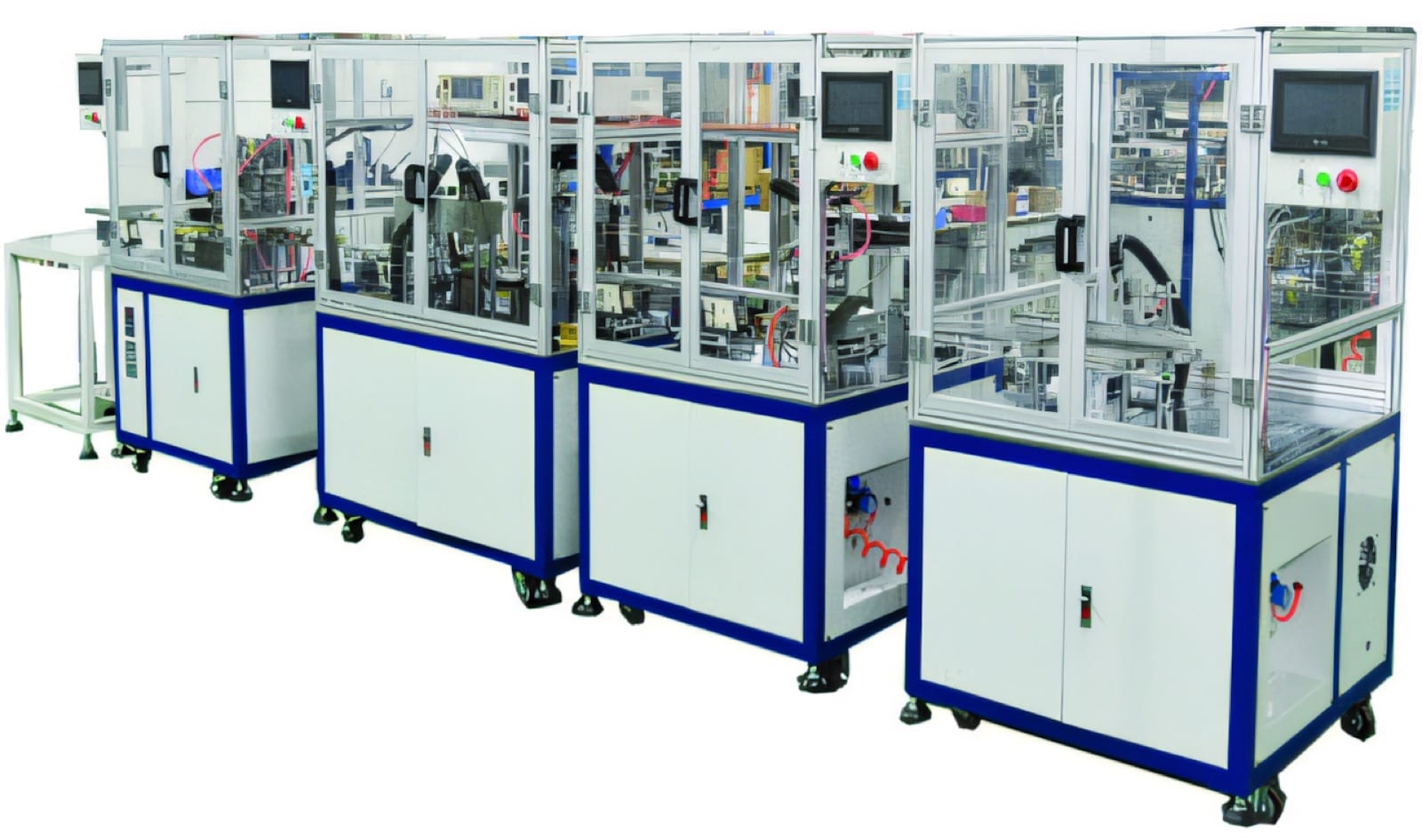
In an automated line, the product recipe should select the approved connections and limits, while pass status follows the component to the next operation. The line must prevent an untested or interrupted part from mixing with accepted production. Store the data required for quality control, troubleshooting and customer records.
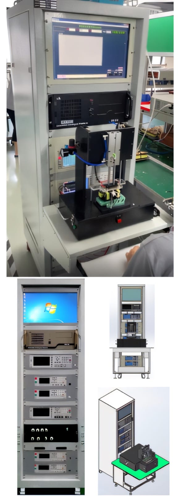
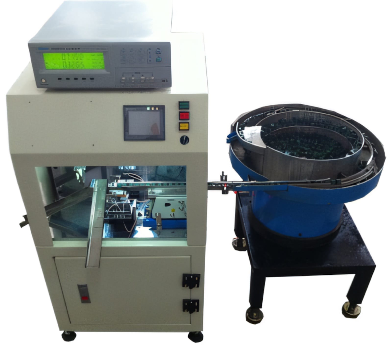
PM Electronics supplies transformer, inductor and combined testing systems that can be configured around the approved test plan and handling method. Final scope is confirmed from the component, connection diagram, safety requirements, target cycle and traceability needs.
Relevant machinery for this process
Explore PME equipment that can support the operations discussed in this guide. Final machine selection should be confirmed against your component, materials and target output.
Plan the next step
Discuss your component and production target with PME.
Share a drawing, sample, current process and expected output. We can help map the right machines and level of integration.