
Start with the electrical and mechanical joint
The choice between spot welding and soldering should come from the joint design, materials and service conditions. Both processes can create reliable electrical connections, but they form the joint differently and place different demands on terminal geometry, surface condition and inspection.
Define conductor material and coating, terminal thickness, required resistance, pull strength, thermal exposure and downstream encapsulation. A process that works well for one relay terminal can be unsuitable for a fine magnet wire or heat-sensitive bobbin.
Choose soldering for wettable terminals and flexible geometry
Soldering uses a filler alloy to wet prepared surfaces. Dip soldering can process several terminals together and is well suited when flux, immersion depth, dwell and drainage can be controlled. It can accommodate useful geometric variation, but the component must tolerate the thermal cycle and any required cleaning.
Joint quality depends on solderability, flux condition and bath control. The process also introduces consumables and requires management of solder level, dross and alloy composition. Inspection should look beyond appearance to the product’s electrical and mechanical acceptance criteria.
Choose spot welding for localized fusion
Resistance spot welding passes current through a clamped contact area to create localized heat and a fused joint. It can offer a fast cycle without solder or flux and limits heating away from the electrode area when the materials and geometry are suitable.
The method needs repeatable contact pressure, electrode condition and part location. Surface coatings, thickness variation and poor fit-up can change energy delivery. Electrode wear is a production variable, so cleaning, dressing or replacement limits belong in the control plan.
- Material and plating compatibility
- Required joint resistance and pull strength
- Allowed heat near insulation or plastic
- Electrode access and maintenance frequency
Prove the process with representative samples
Compare both options using real material lots and the expected dimensional range. Test electrical resistance, pull or peel behaviour, section quality where appropriate, cycle time and results after the product’s thermal or environmental qualification.
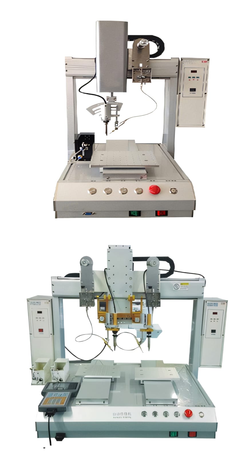
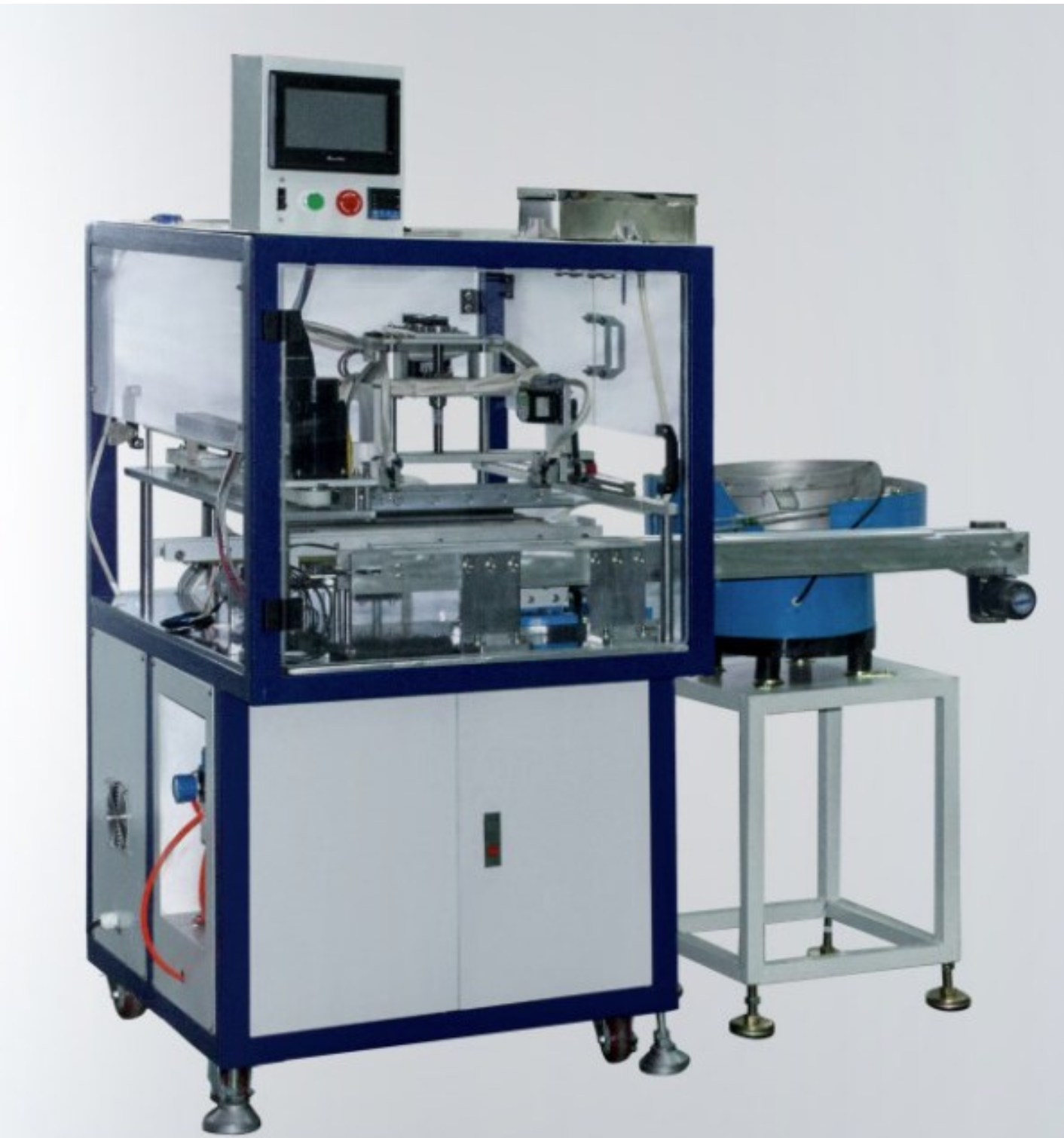
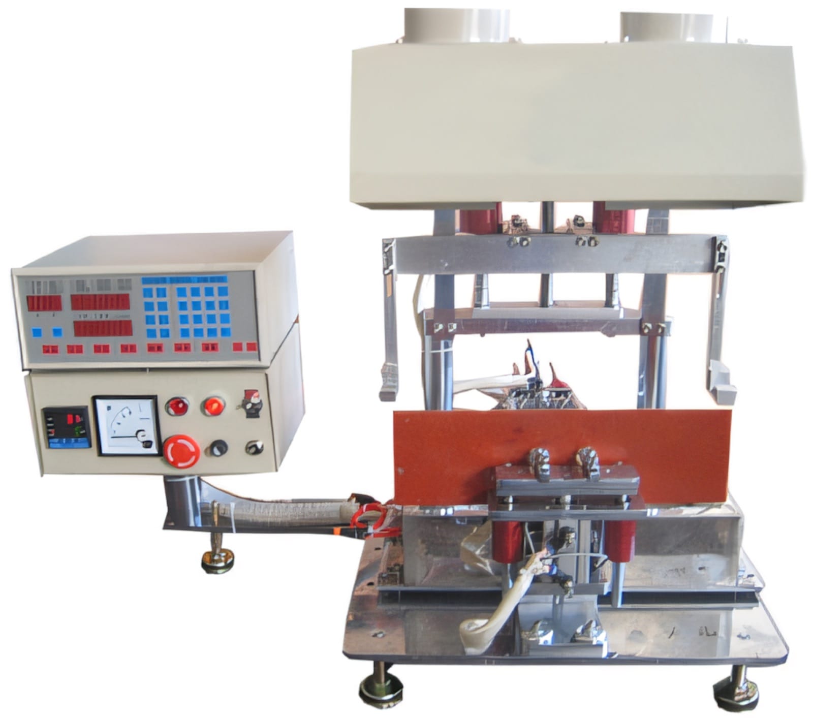
PME offers automatic spot-welding and multiple dip-soldering configurations. A joining trial should select the process first, then define feeding, fixturing, controls and inspection around the joint that the finished component actually requires.
Relevant machinery for this process
Explore PME equipment that can support the operations discussed in this guide. Final machine selection should be confirmed against your component, materials and target output.
Plan the next step
Discuss your component and production target with PME.
Share a drawing, sample, current process and expected output. We can help map the right machines and level of integration.