
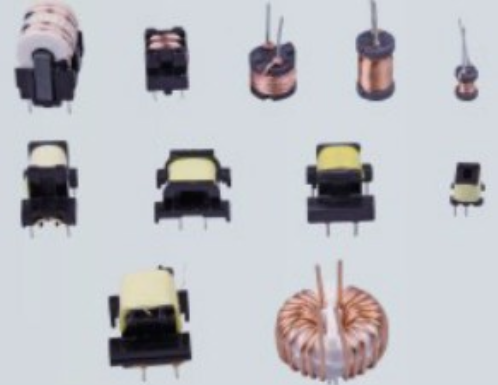
Use the fixture to define the soldering geometry
An automatic dip-soldering machine can repeat movement accurately only when the fixture presents each terminal in the same position. The fixture establishes immersion depth, angle, spacing and drainage behaviour. If parts float, tilt or sit against inconsistent surfaces, machine settings alone cannot produce stable joints.
Start from the component drawing and approved soldered sample. Identify the functional datums, joint area, heat-sensitive surfaces and allowed solder height. Include the normal variation of terminals and moulded parts so the fixture controls what matters without clamping every dimension rigidly.
- Repeatable location from functional datums
- Clear access for flux and solder
- Protection for heat-sensitive areas
- A defined path for excess solder to drain
Support the component without trapping solder or flux
Clamps and nest surfaces should hold the part securely through acceleration, rotation and dipping while leaving the joint area open. Pockets that collect flux or solder can create contamination, slow drainage and change the thermal response as deposits build. Tooling should also avoid scraping enamel wire or loading delicate terminals.
Where several components are processed together, keep their terminal heights consistent and allow enough spacing to prevent bridging between parts. Confirm that a missing or incorrectly seated component can be detected before the fixture enters the bath.
Design for heat, contamination and regular cleaning
Fixture materials and finishes must tolerate the qualified soldering process and cleaning method without distorting, shedding contamination or wetting in unwanted areas. Thermal expansion can change immersion position on long or multi-part fixtures, so the design should be proven after repeated cycles rather than checked only when cold.
Make areas that accumulate dross and residue visible and accessible. A fixture that takes too long to clean is likely to remain in service beyond its stable condition. Define cleaning frequency, inspection points and replacement criteria during process development.
- Temperature-compatible fixture materials
- Replaceable wear and contact elements
- Accessible residue and dross collection areas
- Reference features for checking alignment
Reduce changeover with controlled interfaces
For a mixed product schedule, separate machine interfaces from product-specific tooling. Quick-change fixtures should locate positively, lock securely and identify the correct product recipe. Mechanical coding, sensors or fixture identification can prevent a tool from running with incompatible immersion and timing settings.
Keep connections, fasteners and operator actions simple enough to perform consistently. The target is not only a short changeover; it is a changeover that returns the process to its approved condition without trial-and-error adjustment or a hidden alignment check.
Validate the fixture as part of the soldering process
Run representative parts at every fixture position and compare flux coverage, solder height, joint appearance and electrical result. Include repeated heating, normal cleaning and several changeovers. If one position behaves differently, investigate local alignment, thermal behaviour and drainage before widening the machine recipe.
PM Electronics configures soldering fixtures around the component, loading method and required output. From three-way loading and fixture-down machines to four- and six-station systems, the tooling is developed as part of the complete fluxing, dipping, unloading and maintenance process.
Relevant machinery for this process
Explore PME equipment that can support the operations discussed in this guide. Final machine selection should be confirmed against your component, materials and target output.
 PME AUTOMATION
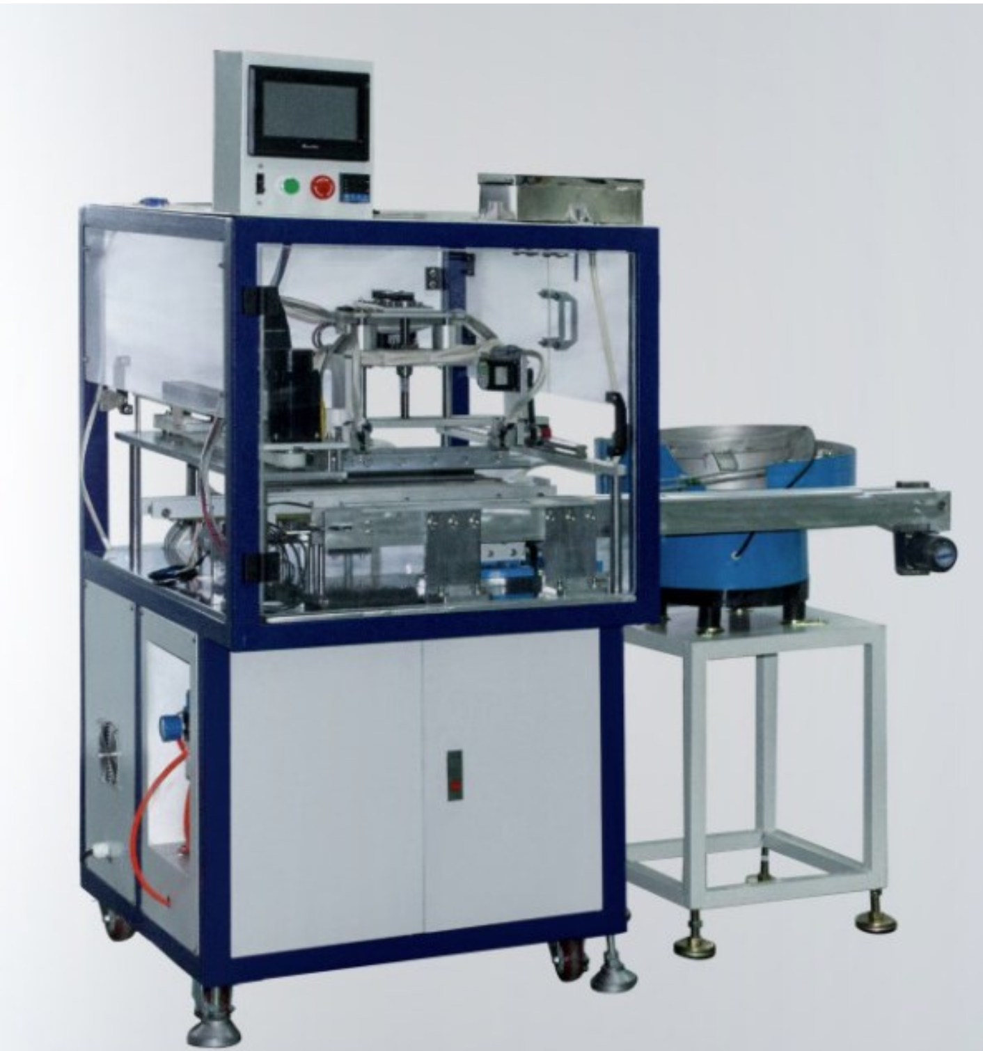
Auto Soldering Machine (3 Ways Loading Type)
View machine ↗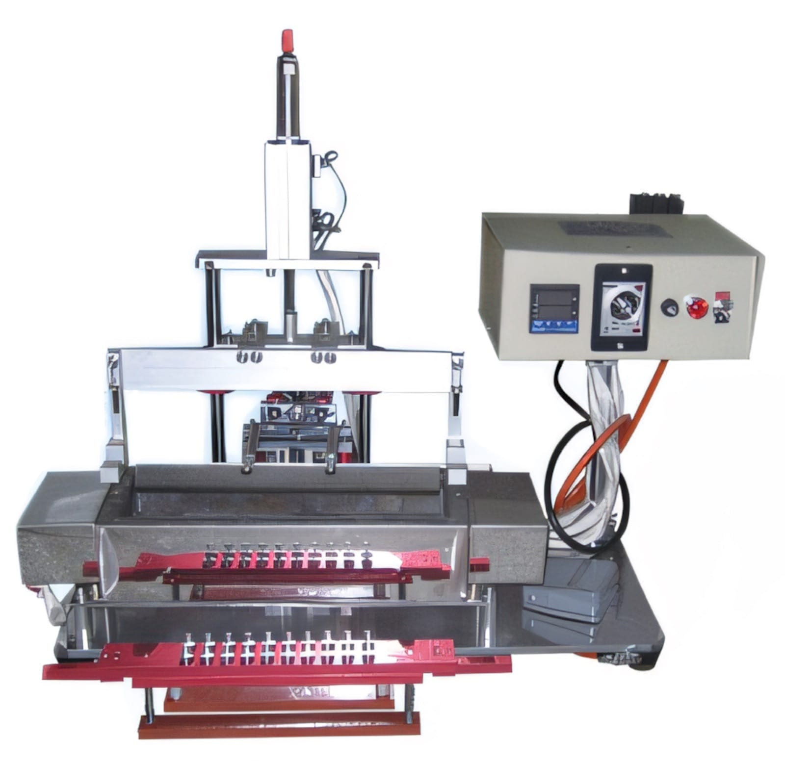 PME AUTOMATION
Auto Dip Soldering Machine — Fixture Down Soldering
View machine ↗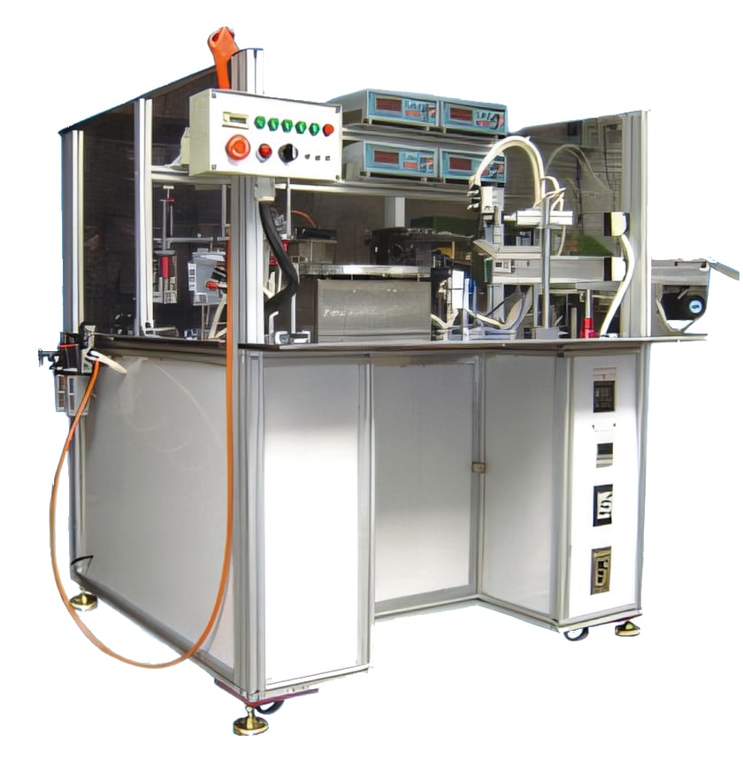 PME AUTOMATION
Six Station Auto Dip Soldering Machine
View machine ↗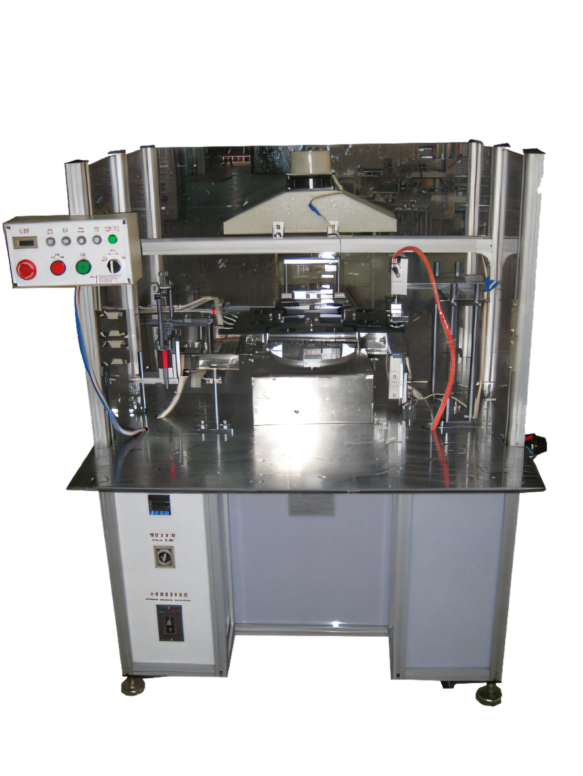 PME AUTOMATION
Four Station Auto Dip Soldering Machine
View machine ↗Plan the next step
Discuss your component and production target with PME.
Share a drawing, sample, current process and expected output. We can help map the right machines and level of integration.