
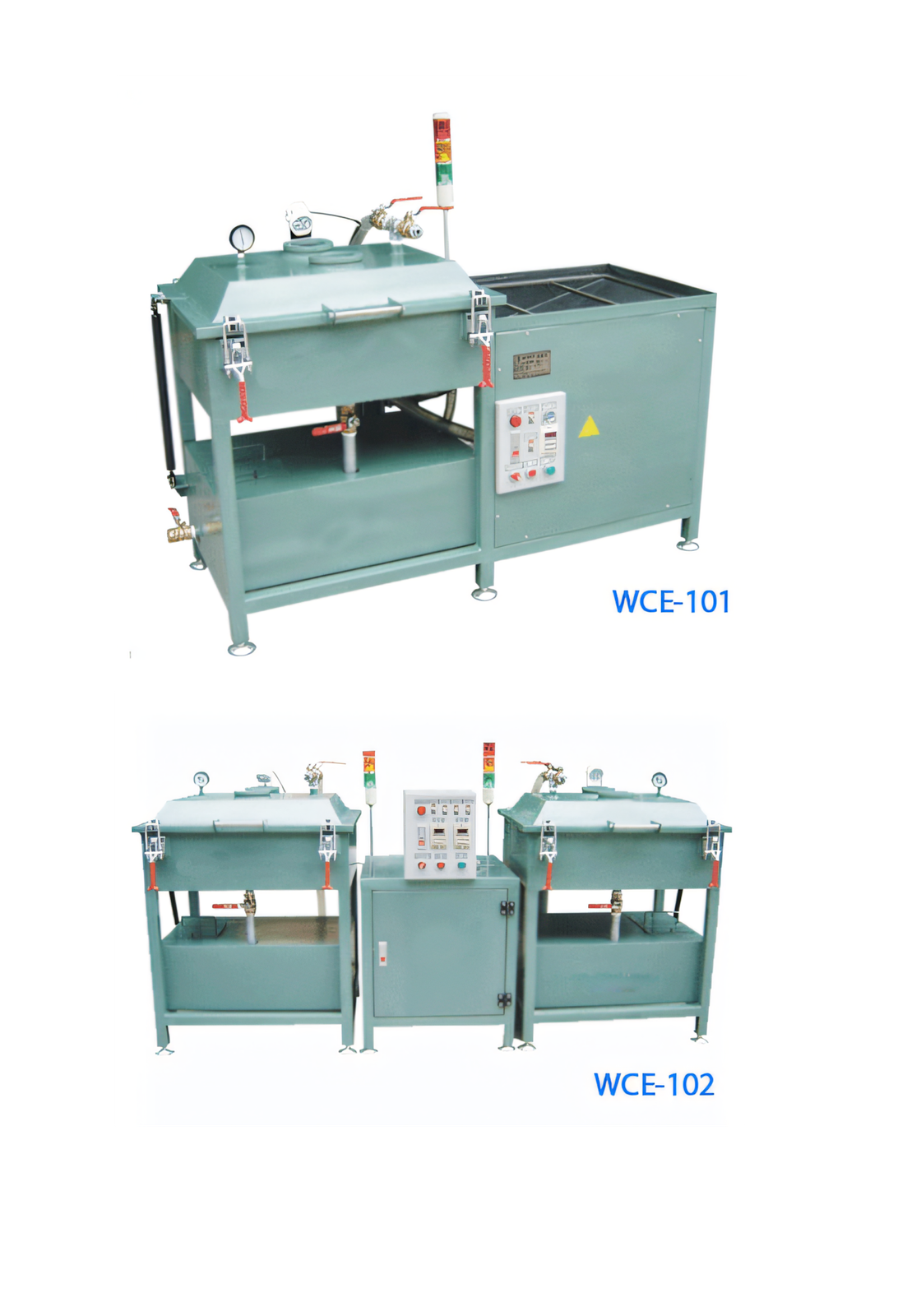
Clarify what each tank does
The labels single-tank and double-tank are useful starting points, but equipment layouts differ. One design may use a single process vessel, while another separates the working chamber from material storage or adds a second vessel to support transfer and scheduling. Ask the supplier to show the exact flow path, valve sequence and cleaning method.
Build the comparison around the proposed cycle. Identify where components are loaded, where resin is held, how vacuum is applied, how material returns and what happens during a colour or chemistry change. A clear process diagram prevents assumptions based only on the model name.
When a single-tank system can be practical
A single-tank arrangement can suit a focused product family, moderate batch demand and a stable impregnant. Fewer vessels and transfer paths can simplify installation, operator training and routine cleaning. It may also reduce the amount of material held inside the equipment.
The trade-off can be less separation between process steps and fewer opportunities to prepare one operation while another is underway. Check whether loading, filling, draining and material conditioning compete for the same vessel time, because the slowest repeated activity will determine batch output.
When a double-tank layout can add value
A double-tank system may support a more controlled material-transfer sequence, additional storage or greater production flexibility, depending on its design. It can be attractive when batch frequency is high, the working material needs managed storage or the process benefits from separating component treatment from another function.
Extra capability brings more valves, piping, sensors and surfaces to maintain. Review drainability, dead volume, filter access and the procedure for removing old material. A larger system only improves output when its operating sequence actually reduces the production constraint.
- Batches required per shift
- Material storage and conditioning needs
- Cleaning and chemistry-change frequency
- Available floor space and utility capacity
Select with a time-and-material study
Calculate the complete batch time, including loading, vacuum preparation, soak, return to pressure, draining, unloading and cleaning. Estimate material retained in the equipment and the labour needed for each routine intervention. This exposes whether the second tank creates real capacity or only additional complexity.
PME offers one- and double-tank vacuum-impregnation equipment for electronics production. Final selection should follow trials with the approved component and resin, confirmation of the vessel functions, and acceptance criteria for penetration, cure, throughput and cleanability.
Relevant machinery for this process
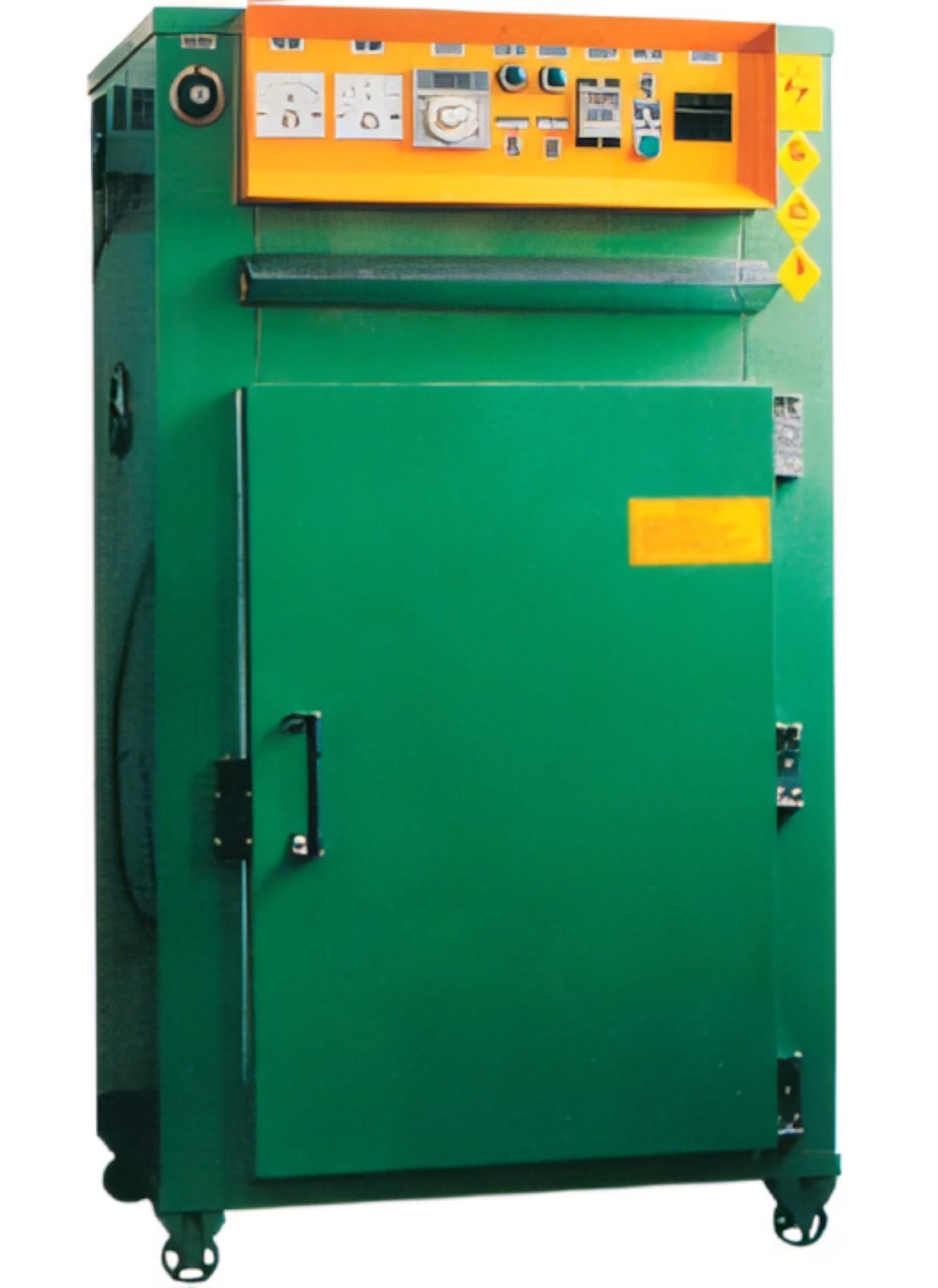
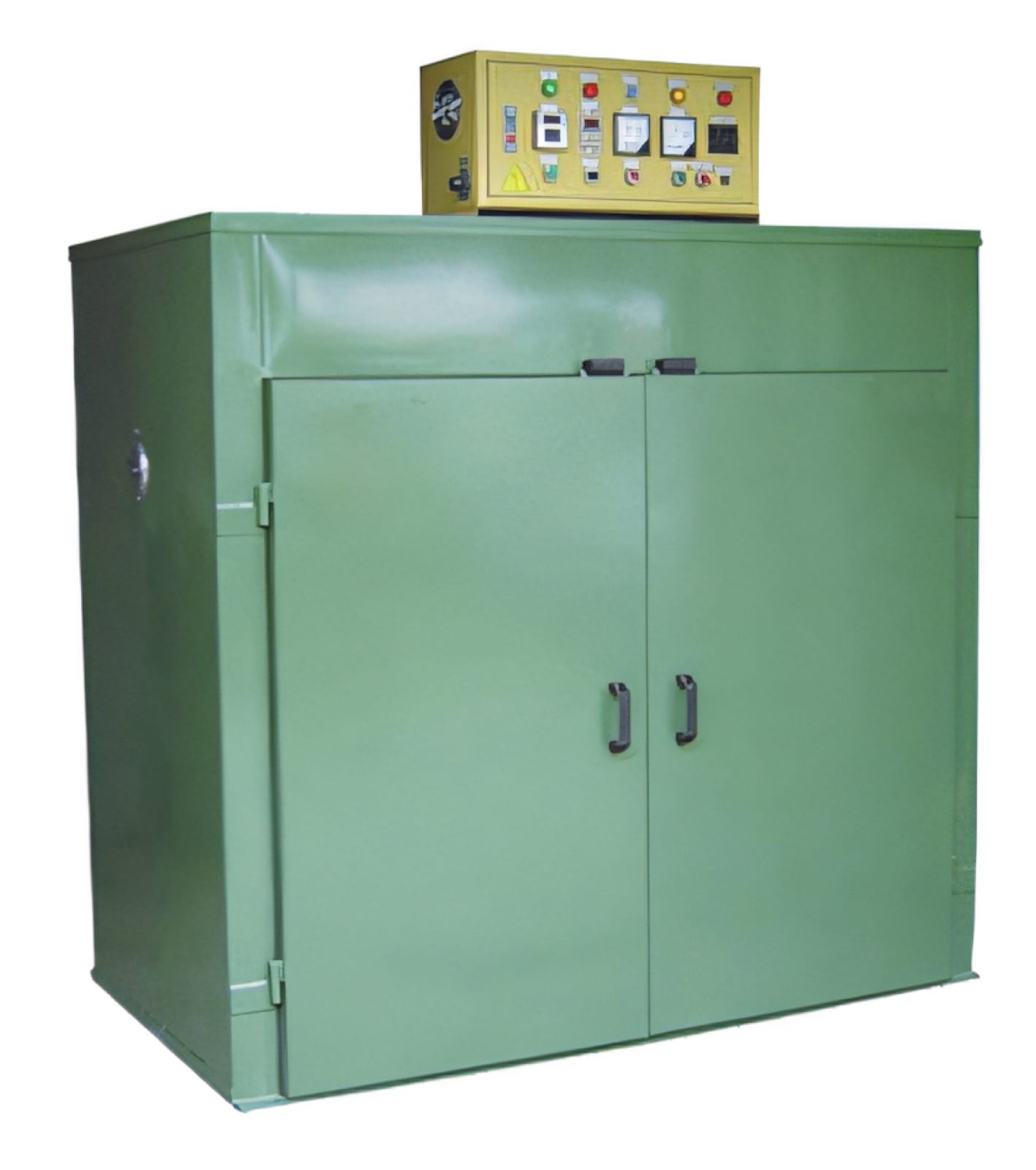
Explore PME equipment that can support the operations discussed in this guide. Final machine selection should be confirmed against your component, materials and target output.
Plan the next step
Discuss your component and production target with PME.
Share a drawing, sample, current process and expected output. We can help map the right machines and level of integration.