
Define the product family and line boundary
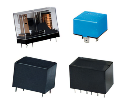
Relay assembly automation should begin with a product-family matrix. List bobbin, pin, coil, yoke, armature, spring, contact and cover variants, then identify which changes require tooling and which can be handled by recipes. A line designed for one stable relay differs from equipment expected to change every shift.
Decide whether the automatic relay production line begins with an empty bobbin, a wound coil or a preassembled magnetic unit. This prevents gaps in scope and clarifies who owns intermediate quality.
Choose feeding and transfer methods around the parts
Small relay components can be bowl-fed, tray-fed or manually presented in guided fixtures. The right method depends on geometry, surface sensitivity, variant count and replenishment frequency. Every feeder needs an escape path for incorrectly oriented parts and accessible recovery.
Transfer should preserve datum and part identity. Pallets provide flexibility and buffering; direct transfer can reduce handling and floor space. Both approaches need clear rules for empty nests, failed parts and restart after a stop.
Balance assembly, joining and testing
The slowest reliable operation sets line output unless parallel stations are used. Measure complete cycles for pin insertion, winding, assembly, soldering and relay testing, including clamp time, verification and unload. A nominally fast station can become the constraint if it needs frequent consumable replenishment.
Use common product recipes so winding parameters, soldering conditions and test limits change together. Pass/fail information should move with each unit, and rejects should enter a controlled location that prevents accidental return.
- Sustained good parts per hour
- Changeover and replenishment workload
- Fault recovery without mixed production
- Traceability required by the customer
Specify acceptance and local support
Run representative materials at target takt and include normal disturbances such as an empty feeder, part misorientation and test failure. Confirm safe recovery, data handling, tooling access and preventive-maintenance tasks before approval.
PME can combine relevant insertion, soldering and relay testing machines with application-specific line engineering. For Indian factories, installation, commissioning, operator training and spare-parts planning should be treated as part of the automation scope.
Relevant machinery for this process
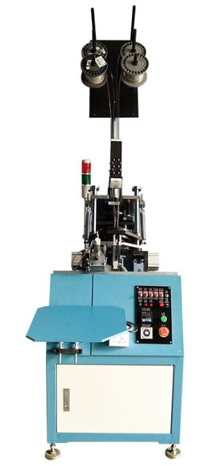
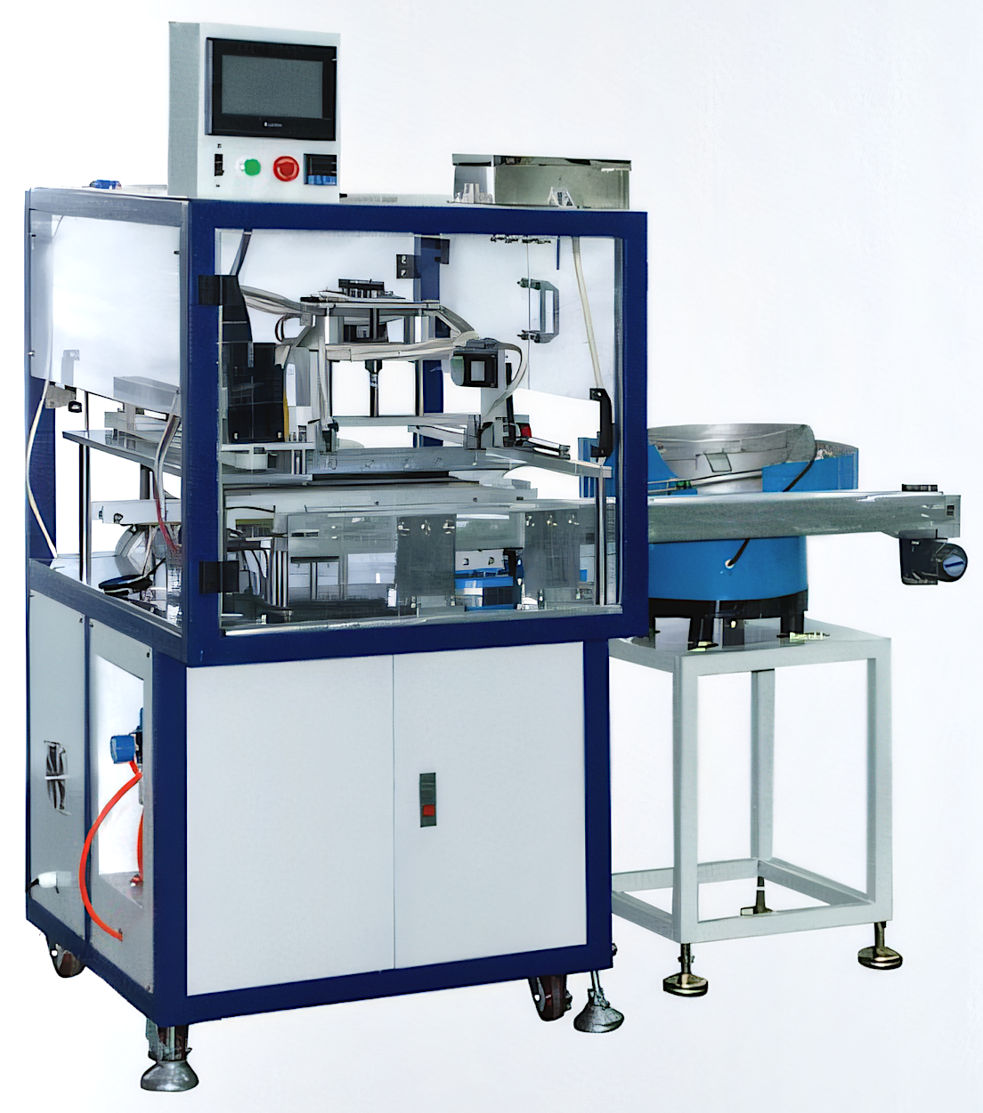
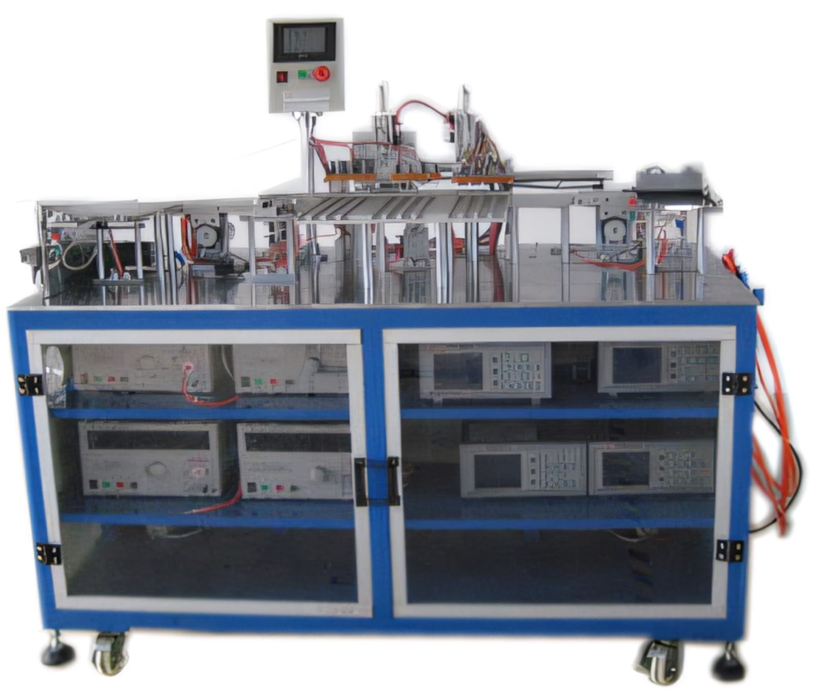
Explore PME equipment that can support the operations discussed in this guide. Final machine selection should be confirmed against your component, materials and target output.
Plan the next step
Discuss your component and production target with PME.
Share a drawing, sample, current process and expected output. We can help map the right machines and level of integration.