
Start with defects that a camera can actually see
Machine vision is most valuable when the defect has a consistent visual signature. Missing pins, incorrect orientation, lead position, tape coverage and gross solder bridging can be strong candidates. Internal electrical faults, weak joints below the visible surface and subtle material changes usually require another test method.
Create an inspection list using approved good parts and real defects from production. For every check, define the feature, acceptable range and business reason for rejecting it. Avoid asking a camera to make a vague judgement such as whether a coil looks good; translate the requirement into position, presence, shape, contrast or measurable coverage.
- Feature to inspect and expected location
- Smallest defect that must be detected
- Normal acceptable appearance variation
- Required action when inspection fails
Present the component in a repeatable position
Good inspection begins with mechanical handling. If the component tilts, rotates or moves between images, the software must tolerate more variation and may become less sensitive to the defect that matters. A nest, conveyor fixture or controlled stop should expose the required surfaces without hiding terminals or casting unwanted shadows.
Inspection is often best placed immediately after the operation that creates the feature. Checking pin presence after insertion or lead position after winding prevents more value being added to a known failure. A final camera can still confirm overall assembly, but it should not replace useful checks earlier in the route.
Engineer lighting before adding software complexity
Lighting determines which features become visible. Bright metal terminals, dark enamel wire, reflective solder and coloured plastics respond differently to direct, diffuse, backlit or angled illumination. Shielding the inspection area from changing factory light often improves reliability more than adding image-processing rules.
Select the camera field of view and resolution from the smallest required defect, then confirm working distance and depth of field. A high-resolution image is not automatically useful if the part moves outside the focus range or reflections erase the edge the system needs to measure.
Validate with good, bad and borderline samples
A vision system should be challenged with normal colour, surface and dimensional variation. Build a controlled sample set containing accepted parts, known failures and borderline conditions near the agreed limit. Repeat the study across fixtures, machine positions and production shifts.
Track false rejects and missed defects separately. Making every limit tighter can reduce escapes but may stop production for harmless appearance variation. The final threshold should reflect the product requirement and the capability of the complete presentation and lighting system, not a single ideal image.
- Repeatability with the same part
- Variation between nests or lanes
- False-reject and false-accept risk
- Response to dirt, glare and gradual tool wear
Connect the decision to controlled part flow
Inspection only protects output when its decision follows the component. Failed or uninspected parts should enter a secure reject location, and the machine should confirm that the reject action occurred. Where traceability is required, save the result and essential measurements without creating an unmanageable archive of images that nobody reviews.
PM Electronics can consider vision checks as part of a pin-insertion, winding, soldering, assembly or testing project when the product and defect are suitable. We combine the camera requirement with practical fixturing, cycle time and reject handling so inspection operates as a production process rather than a separate demonstration.
Relevant machinery for this process
Explore PME equipment that can support the operations discussed in this guide. Final machine selection should be confirmed against your component, materials and target output.
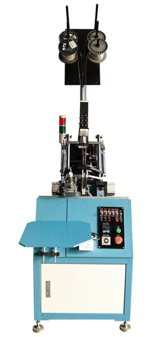 PME AUTOMATION
Auto Pin Inserting Machine
View machine ↗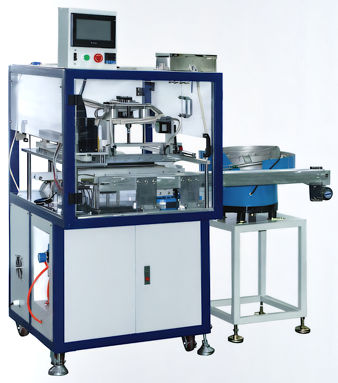 PME AUTOMATION
Fully Auto Dip Soldering Machine — Conveyor Belt Type
View machine ↗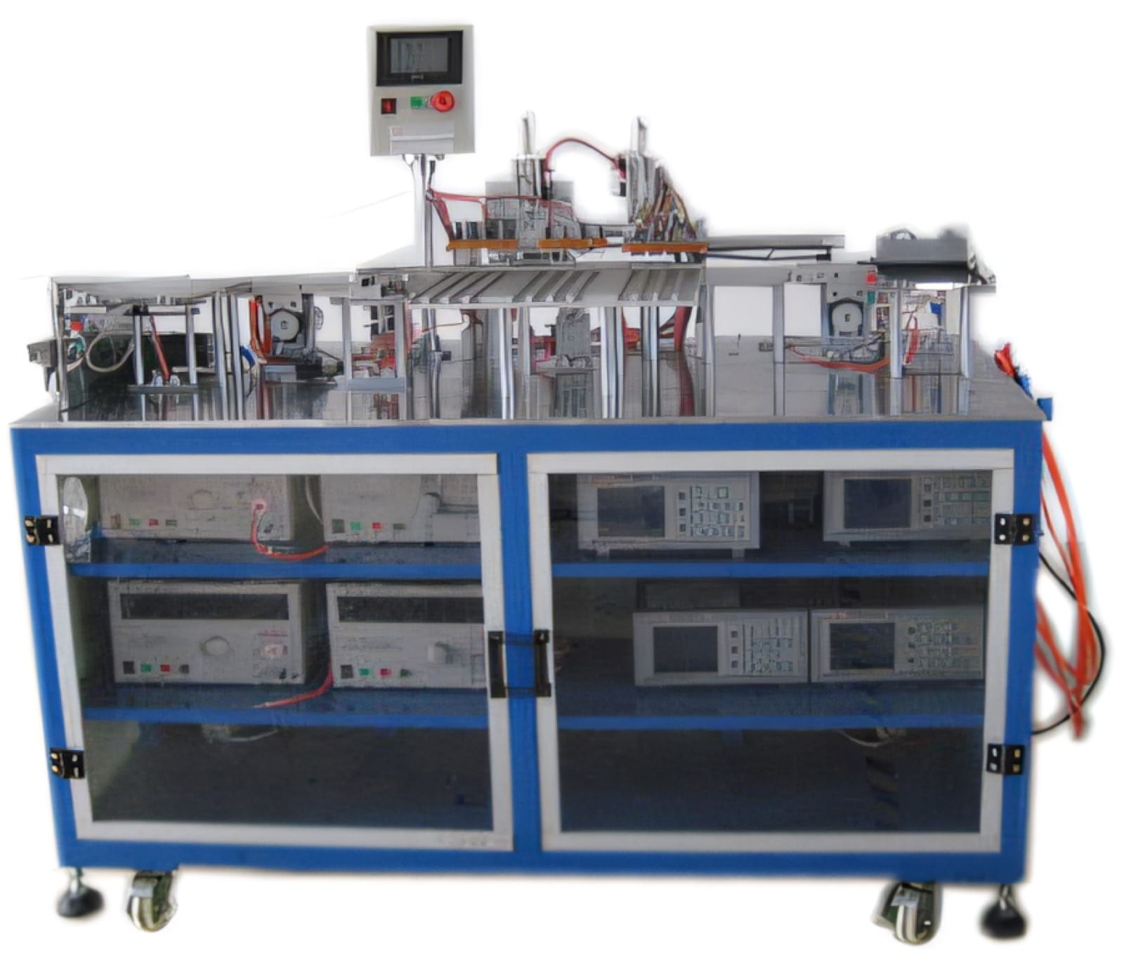 PME AUTOMATION
Fully Auto Relay Testing Machine
View machine ↗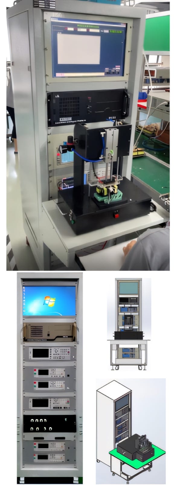 PME AUTOMATION
Combined Testing System — Inductance/CMN/Automobile Electronics
View machine ↗Plan the next step
Discuss your component and production target with PME.
Share a drawing, sample, current process and expected output. We can help map the right machines and level of integration.