
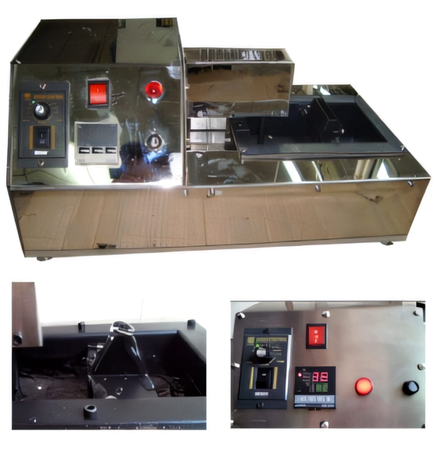
Understand what creates solder dross
Solder dross forms when molten alloy reacts with oxygen and creates an oxide-rich layer at the surface. Some formation is unavoidable, but excessive turbulence, unnecessary surface exposure and poor operating discipline can increase the amount of usable metal removed during cleaning.
Measure the issue before changing the process. Track solder added, dross removed, operating hours and good parts produced. A simple weekly ratio reveals whether the loss is stable or rising and helps separate a real process problem from normal variation in cleaning technique.
Stabilize temperature, level and bath movement
Operate within the approved temperature window for the alloy and component. Excessive heat accelerates oxidation, while an unstable or under-heated bath can damage wetting and tempt operators to extend dwell. Verify the controller against an independent measurement at a defined interval.
Keep the working level consistent and avoid unnecessary agitation of the surface. Fixtures should enter and leave smoothly without dragging oxide into the joint area. If the machine uses a pump or wave, review flow only to the level needed for stable contact rather than maximizing movement.
- Confirm actual temperature and sensor condition
- Maintain a defined solder level
- Minimize avoidable turbulence
- Protect the bath during extended idle periods
Standardize skimming and replenishment
Aggressive skimming can remove good solder with the oxide. Define when cleaning is required, the tool to use and how material should drain before disposal. Operators should never return questionable residues to the pot without an approved recovery method.
Add the correct alloy rather than treating every bar as interchangeable. Copper and other metals can dissolve into a working pot over time and affect wetting behaviour. Periodic composition analysis provides evidence for replenishment or corrective action instead of relying only on joint appearance.
Treat dross as a process-health indicator
A sudden increase can indicate a temperature-control fault, changed alloy, altered cleaning method, unusual downtime or excessive bath movement. Review these events alongside defect and maintenance records rather than managing dross as an isolated housekeeping issue.
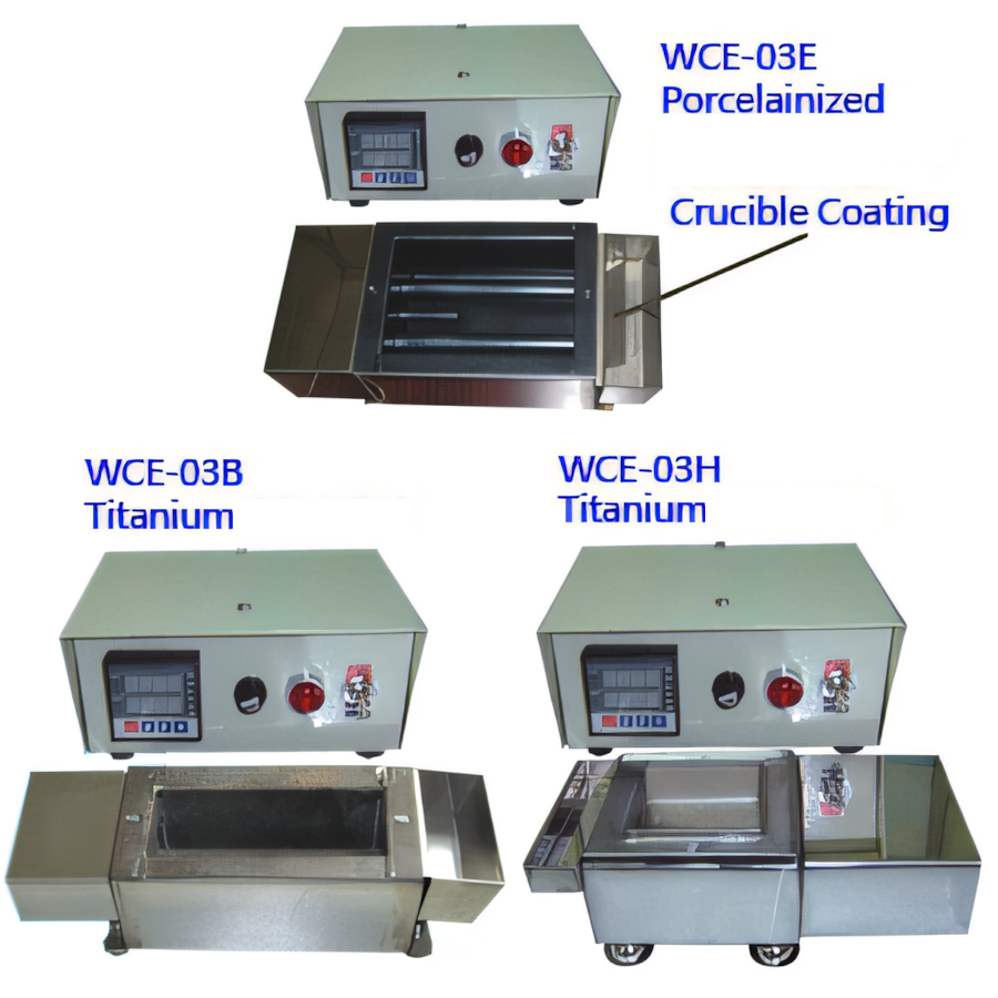
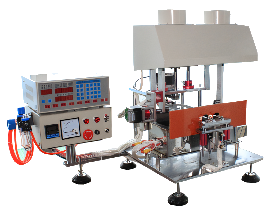
Automatic dip-soldering equipment can improve consistency by controlling immersion and withdrawal, while titanium-crucible solder pots support lead-free production requirements. The machine, alloy, flux and maintenance plan should be qualified together using the manufacturer’s material guidance and the factory’s accepted joint criteria.
Relevant machinery for this process
Explore PME equipment that can support the operations discussed in this guide. Final machine selection should be confirmed against your component, materials and target output.
Plan the next step
Discuss your component and production target with PME.
Share a drawing, sample, current process and expected output. We can help map the right machines and level of integration.