
Match the pot to the alloy and workload
A lead-free solder pot must support the approved alloy, terminal size and production duty without creating unstable temperature or excessive surface exposure. Begin with the largest fixture or component, required immersion depth, parts per cycle and operating hours rather than selecting capacity from the catalogue alone.
More volume provides thermal reserve but also increases warm-up time, alloy inventory and maintenance exposure. The practical size maintains temperature during normal loading while leaving enough clearance for safe fixture movement and surface cleaning.
Review crucible construction and temperature control
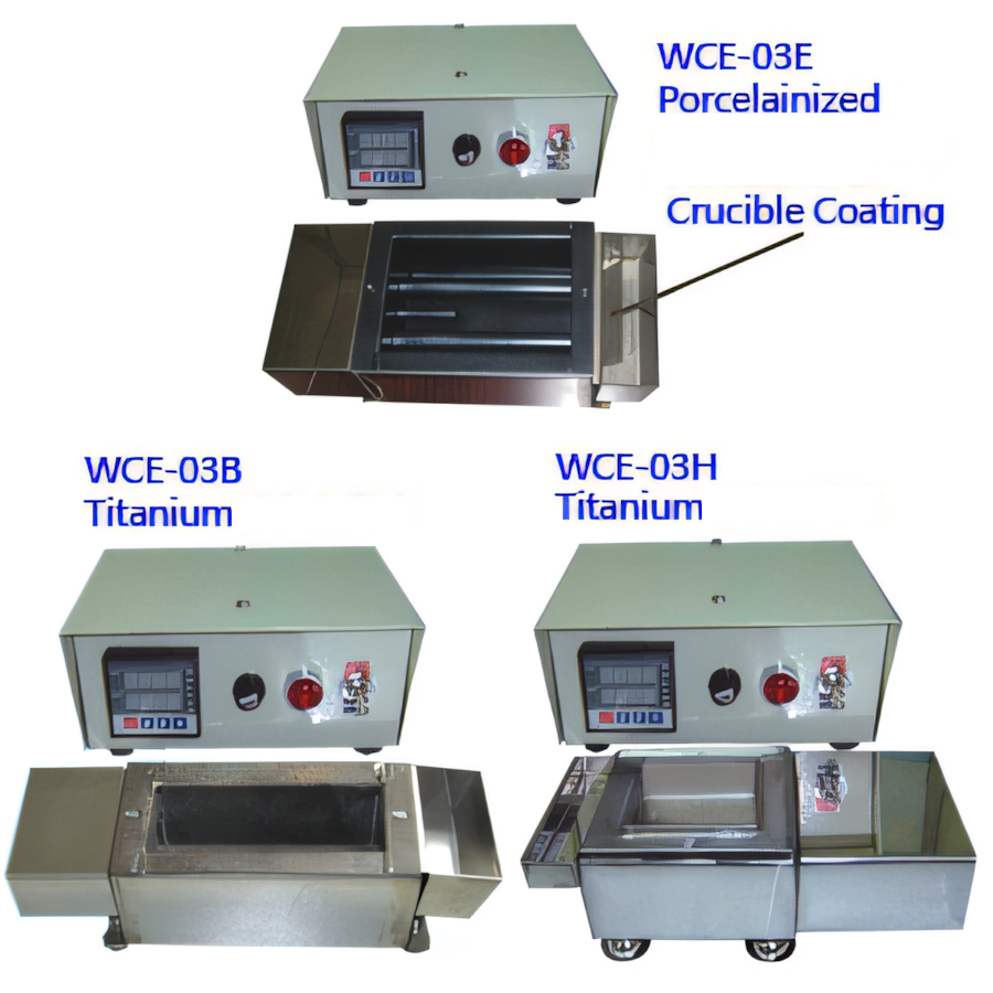
Lead-free alloys can operate at different temperatures and may be more demanding on pot materials than traditional processes. Titanium crucibles are commonly considered where material compatibility and service life are important. Confirm suitability with both the equipment and solder-alloy suppliers.
The controller should hold the approved window, but display stability alone is not proof of bath uniformity. Define sensor placement, independent verification and response after a production load enters the pot. Record warm-up and recovery behaviour during acceptance.
- Approved solder alloy and temperature range
- Crucible material and working dimensions
- Heater capacity and thermal recovery
- Independent temperature-verification method
Plan the fixture, surface and operator interface
The fixture should present terminals at a repeatable depth while protecting the body and insulation. Provide room for drainage and keep clamps away from areas where solder buildup would change the datum. If the operation is manual, assess reach, guarding and the sequence for loading and unloading hot parts.
Surface management matters in lead-free production. Specify how solder is replenished, how dross is removed and where tools are stored. For a wave or pumped design, use only the flow needed to deliver stable contact and avoid unnecessary oxidation.
Validate the complete soldering system
Run the intended alloy, flux, components and fixture at realistic cadence. Confirm joint quality after startup, steady production, replenishment and planned idle periods. Measure actual temperature, recovery time, solder consumption and cleaning effort alongside output.
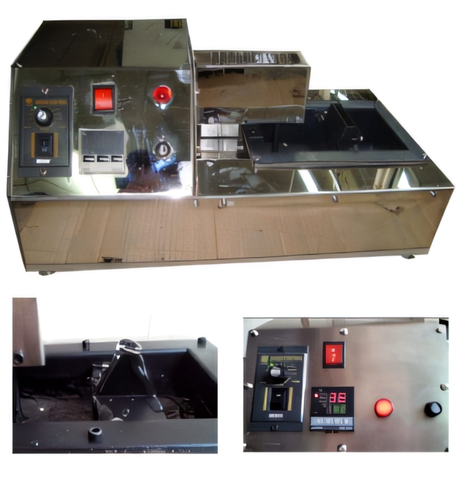
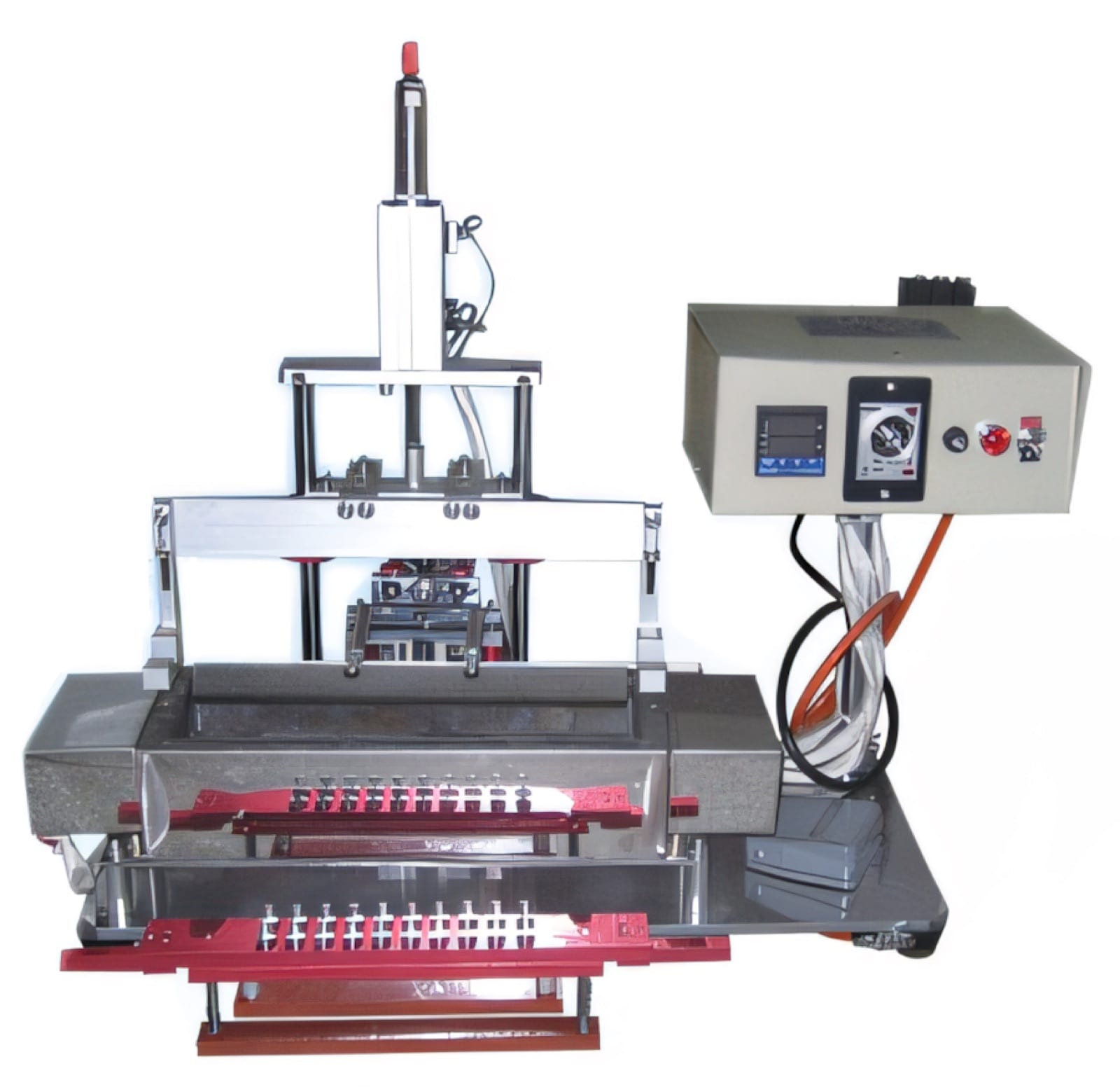
PME offers porcelainized titanium dip pots and a lead-free titanium-crucible surge-wave soldering pot, as well as automatic machines that add controlled fluxing, immersion and unloading. Selection should follow the component trial and the factory’s process-control plan.
Relevant machinery for this process
Explore PME equipment that can support the operations discussed in this guide. Final machine selection should be confirmed against your component, materials and target output.
Plan the next step
Discuss your component and production target with PME.
Share a drawing, sample, current process and expected output. We can help map the right machines and level of integration.