
Locate the break before changing the recipe
A broken wire is the final event in a chain of conditions. The cause may be excessive tension, a damaged guide, a poor spool, a sharp bobbin edge or a sudden speed change. Increasing or decreasing one setting without locating the failure point can hide the symptom while leaving the underlying risk in place.
Preserve the broken ends and record where the wire failed. A break near the payoff suggests a different problem from a break at the nozzle, terminal or winding pack. Note the spindle, wire lot, spool position, machine recipe and point in the cycle so repeated events can be compared instead of treated as isolated stops.
- Break position along the wire path
- Machine step, speed and spindle number
- Wire supplier, lot and spool condition
- Guide, nozzle and tensioner condition
Inspect the complete material path
Magnet wire should leave the spool, pass through the tension system and reach the winding point without rubbing a sharp edge or changing direction unnecessarily. Ceramic eyelets, pulleys and guide tubes need smooth surfaces and correct alignment. A small chip can damage enamel repeatedly before the conductor finally separates.
Check that the spool unwinds freely and cannot trap wire under a neighbouring turn. Payoff behaviour changes as the spool empties, so a setup that runs well at the beginning may become unstable later. Clean dust and enamel residue from the path and replace worn elements rather than polishing them indefinitely without a dimensional check.
Control tension as a dynamic condition
A single static tension reading does not describe high-speed winding. Tension rises and falls during acceleration, traverse reversal, terminal wrapping and emergency deceleration. The tensioner must suit the wire diameter, spool arrangement, speed range and movement profile, with enough response to absorb short disturbances.
Measure tension under representative motion when possible and compare spindles. A stable average with large peaks can still break fine wire or stretch the conductor. Settings should remain within the approved process window for the product and material rather than being increased simply to make the winding pack look tighter.
Use speed profiles that protect difficult transitions
Maximum spindle speed is rarely required through the entire cycle. Starts, stops, flange approaches, crossovers and terminal movements often need controlled acceleration or a lower local speed. A well-designed recipe uses speed where the path is stable and reduces mechanical shock where the wire changes direction.
Review nozzle clearance and traverse timing at the same time. If the guide reaches a flange late, the wire may climb, snag or be pinched by following turns. Correcting the path normally provides a more durable result than lowering the complete cycle to compensate for one unstable movement.
- Gentle acceleration for fine or fragile wire
- Controlled traverse reversal near flanges
- Reduced speed for lead and terminal movements
- A defined response to wire-break detection
Prove the correction across a real production run
After correcting the suspected cause, run long enough to include spool depletion, normal replenishment and the expected operating temperature. Check winding appearance, conductor resistance and enamel condition as well as the number of breaks. A process that avoids breaks by creating loose or damaged coils is not a successful correction.
PME winding machines can be configured around the component, wire range, spindle count and handling sequence. Sharing failed samples, wire data and a short video of the event helps our team separate material, tooling and machine causes before recommending a recipe or hardware change.
Relevant machinery for this process
Explore PME equipment that can support the operations discussed in this guide. Final machine selection should be confirmed against your component, materials and target output.
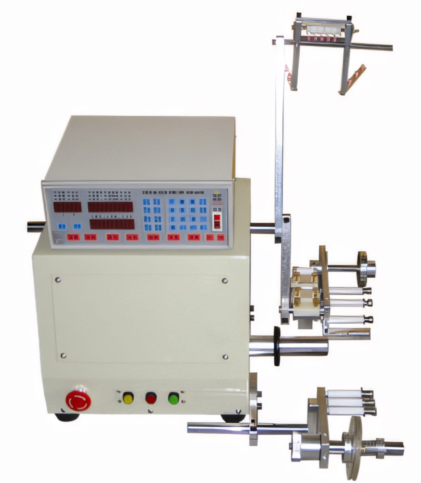 PME AUTOMATION
CNC Auto Winding Machine — 1 Spindle
View machine ↗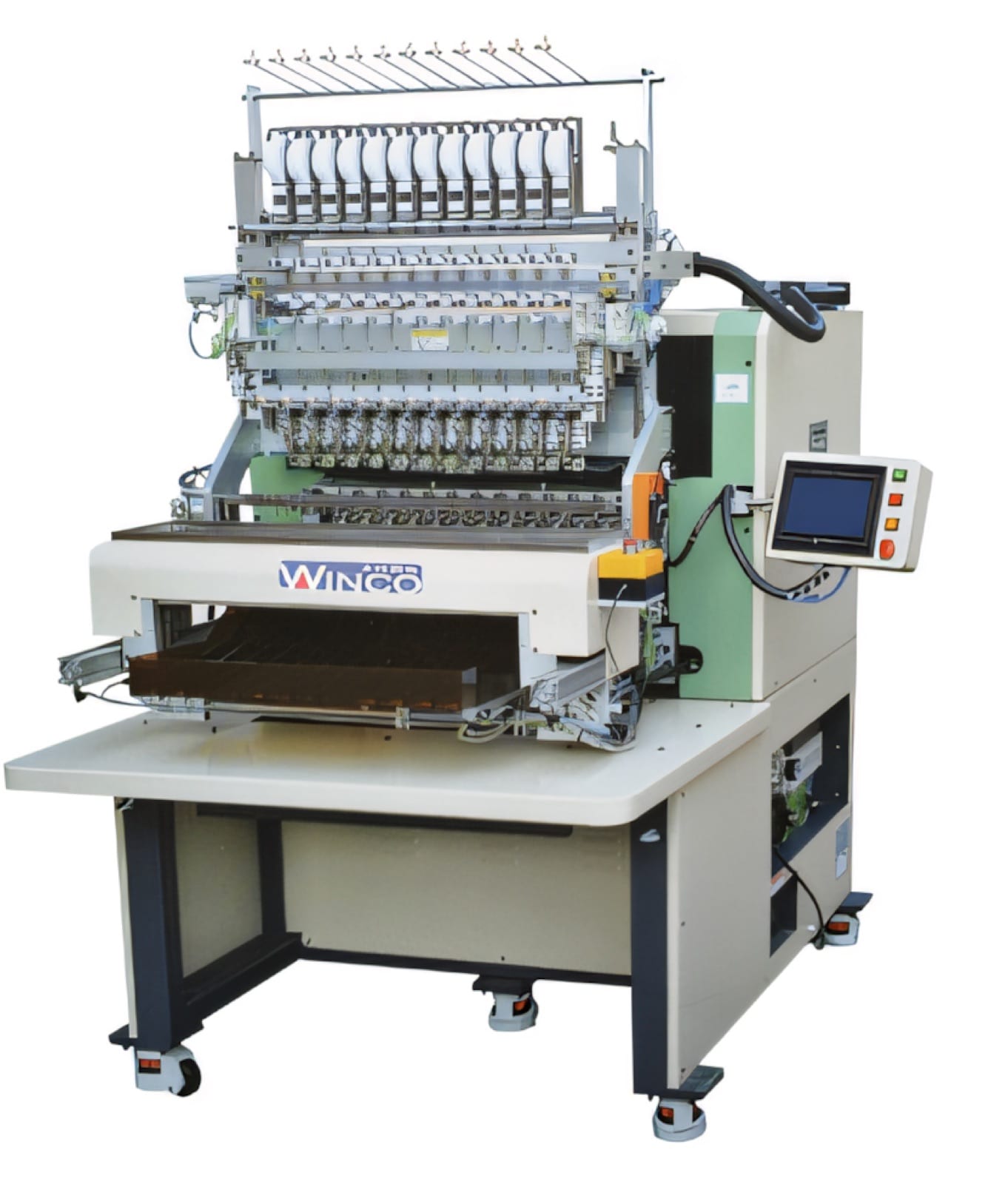 PME AUTOMATION
8/12/16/20 Spindles Auto Axis Winding Machine
View machine ↗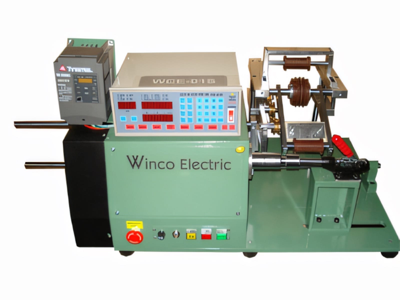 PME AUTOMATION
Digital Large Torque Winding Machine
View machine ↗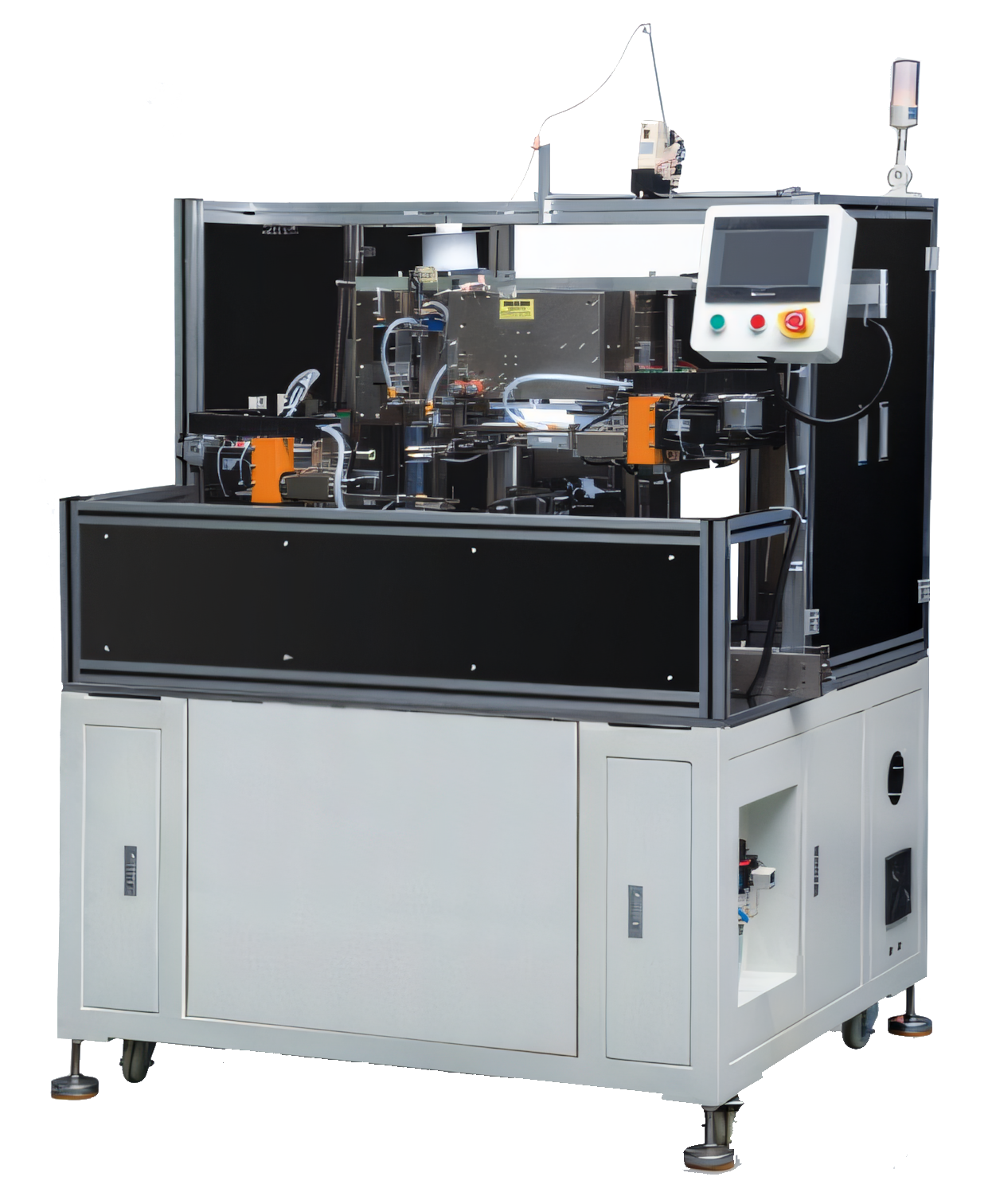 PME AUTOMATION
Auto Tube Insert, Winding & Taping Machine
View machine ↗Plan the next step
Discuss your component and production target with PME.
Share a drawing, sample, current process and expected output. We can help map the right machines and level of integration.