
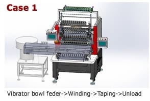
Translate the winding specification into a program
Transformer coils are wound by rotating a bobbin or winding former while guiding magnet wire across the available width. The program controls turns, direction, spindle speed, traverse pitch, acceleration and the positions used for start and finish leads. Multi-winding designs may pause for insulation tape, lead routing or a change of wire.
The transformer coil winding process must be derived from the drawing and approved sample. Turn count alone is not enough: the program also needs layer pattern, edge clearance, crossover position, lead length and any section-winding requirements.
Control tension across the full cycle
Excessive tension can stretch fine wire, damage insulation or deform a bobbin. Low or unstable tension can create loose turns, poor layer formation and unpredictable dimensions. The tension system must remain stable during acceleration, deceleration and spool-diameter change—not only at constant speed.
A suitable transformer coil winding machine should match the wire range and torque demand. Review wire guides, break detection, spool change procedure and the way the machine protects the wire during starts, stops and terminal handling.
- Verify tension with the actual production wire
- Use smooth guide paths with appropriate radii
- Set acceleration as carefully as maximum speed
- Inspect tension hardware as a preventive-maintenance item
Recognize the defect pattern
Common transformer winding defects include crossed turns, uneven layers, loose windings, damaged enamel, incorrect lead position and turn-count errors. Their causes may include unsuitable traverse settings, inconsistent bobbins, worn guides, poor tension control or an incorrect recipe.
Treat the defect location as evidence. A repeatable issue at one edge suggests a different cause from random loose turns throughout the coil. Record the machine program, material lot and operator intervention so corrective action is based on production data.
Choose flexibility or parallel output deliberately
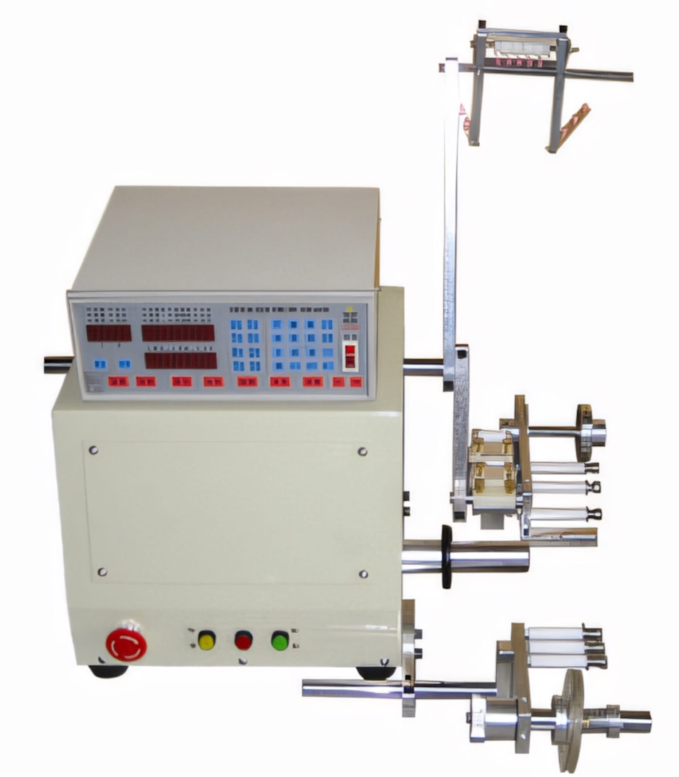
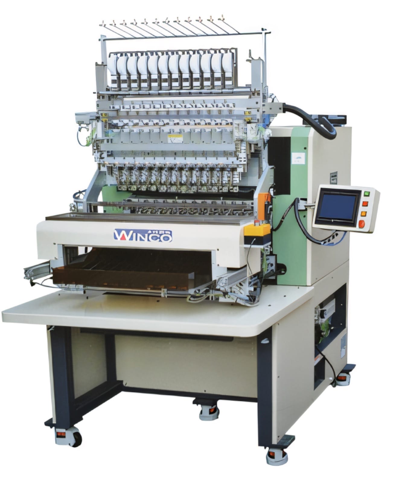
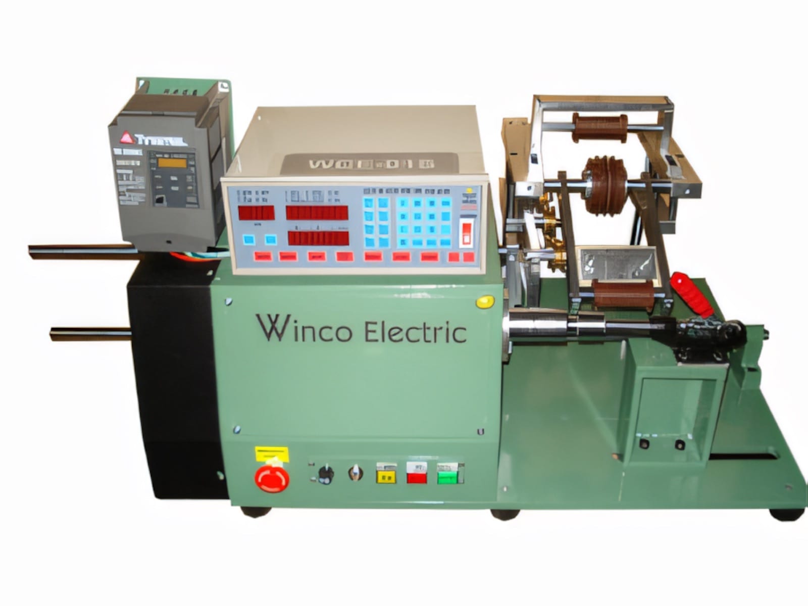
A single-spindle CNC winding machine gives direct access for development, lower-volume work and frequent changes. An 8, 12, 16 or 20 spindle automatic coil winding machine can increase output when parts, tooling and material presentation are consistent across all positions.
PME can review drawings and samples to compare these architectures. The selection should be validated against the hardest wire and part variant, then proven with the planned taping, soldering and testing route.
Relevant machinery for this process
Explore PME equipment that can support the operations discussed in this guide. Final machine selection should be confirmed against your component, materials and target output.
Plan the next step
Discuss your component and production target with PME.
Share a drawing, sample, current process and expected output. We can help map the right machines and level of integration.