
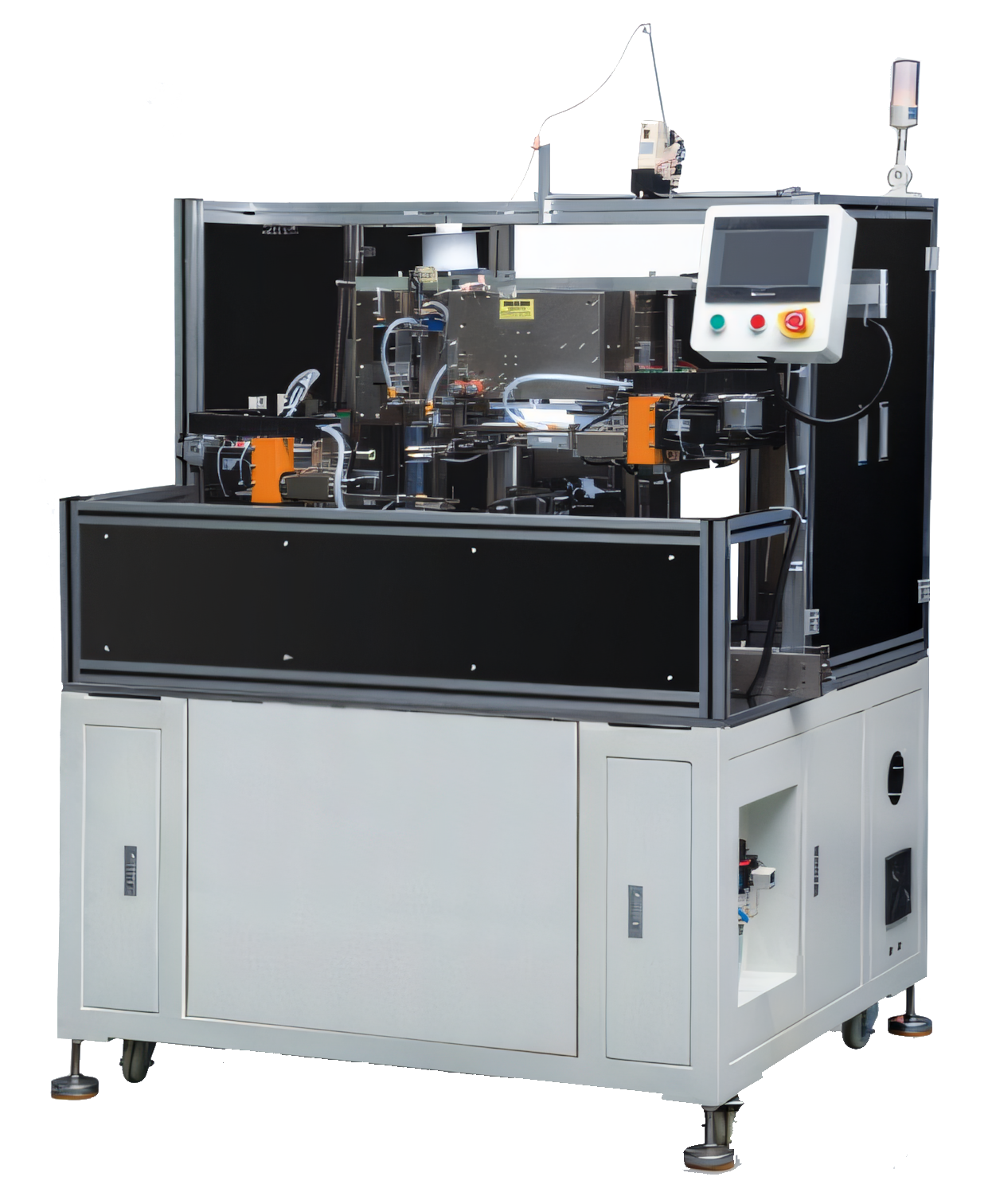
Balance the three process cycles
Winding, soldering and testing rarely have identical cycle times. Start by measuring the realistic cycle for each operation, including loading, clamping, verification and unloading. The slowest repeatable process sets the base takt unless stations operate in parallel.
Small controlled buffers may be useful, but large buffers can hide faults and create mixed batches. The line layout should keep flow visible and make blocked or starved conditions easy to diagnose.
Design a stable part-transfer interface
The wound coil must arrive at soldering with the correct orientation, wire position and terminal presentation. After soldering, the joint must cool or stabilize sufficiently before the test fixture makes contact.
Nests, pallets, conveyors or direct pick-and-place transfer can be used. The best method protects delicate wire, preserves orientation and allows a failed part to leave the line without stopping all other stations.
- Consistent datum and clamping points
- Part-present and orientation checks
- Pass/fail status carried between stations
- Accessible reject and recovery locations
Use common recipes and line control
A line recipe should link the winding program, solder parameters and electrical test limits for one product. This reduces the risk of running the right part with the wrong station settings.
The control architecture also needs defined fault behaviour. Decide whether a station stops the entire line, completes the current cycle or diverts a part. Clear alarms should tell the operator what happened and what safe recovery action is expected.
Validate the line as one system
Individual station acceptance is not enough. Run the complete route at target takt and observe material replenishment, changeover, reject handling and fault recovery. Confirm that process heat, vibration or handling at one station does not influence the next.
Final acceptance should combine output, quality and usability. A line that meets cycle time but is difficult to replenish or recover will not sustain that result on the production floor.
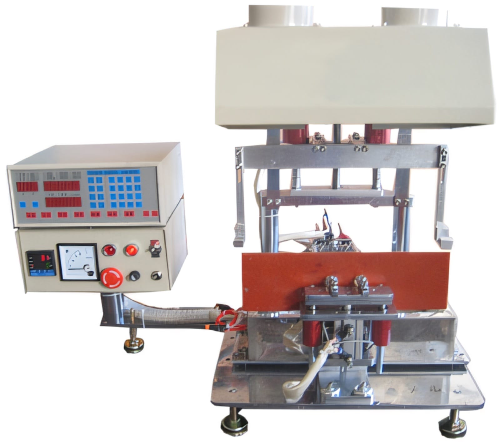
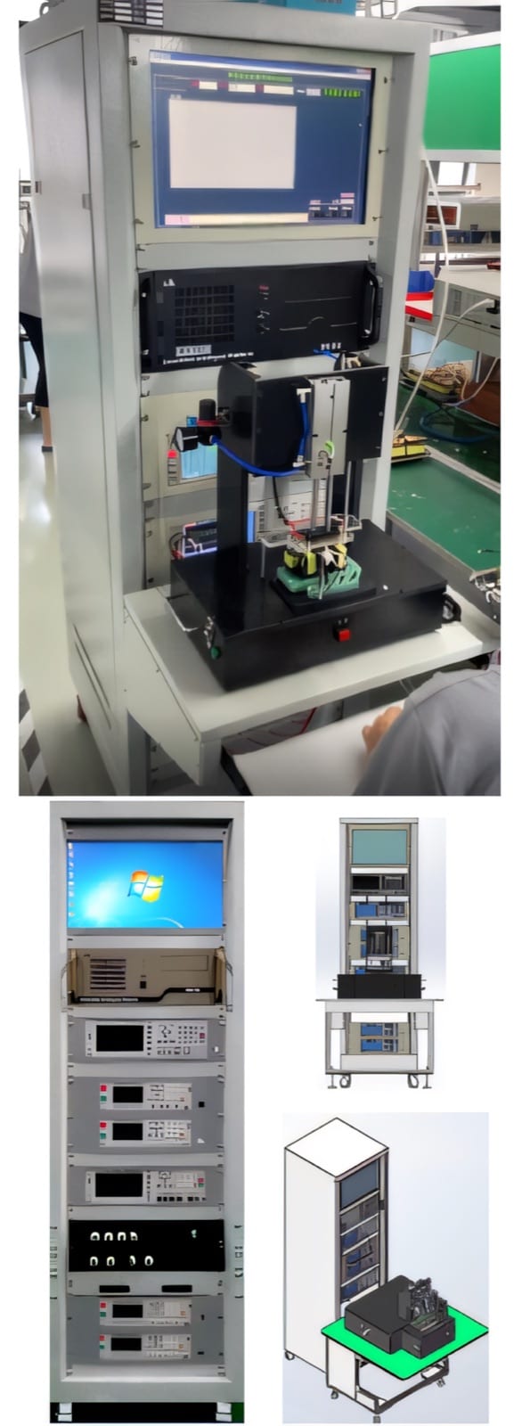
Relevant machinery for this process
Explore PME equipment that can support the operations discussed in this guide. Final machine selection should be confirmed against your component, materials and target output.
Plan the next step
Discuss your component and production target with PME.
Share a drawing, sample, current process and expected output. We can help map the right machines and level of integration.