
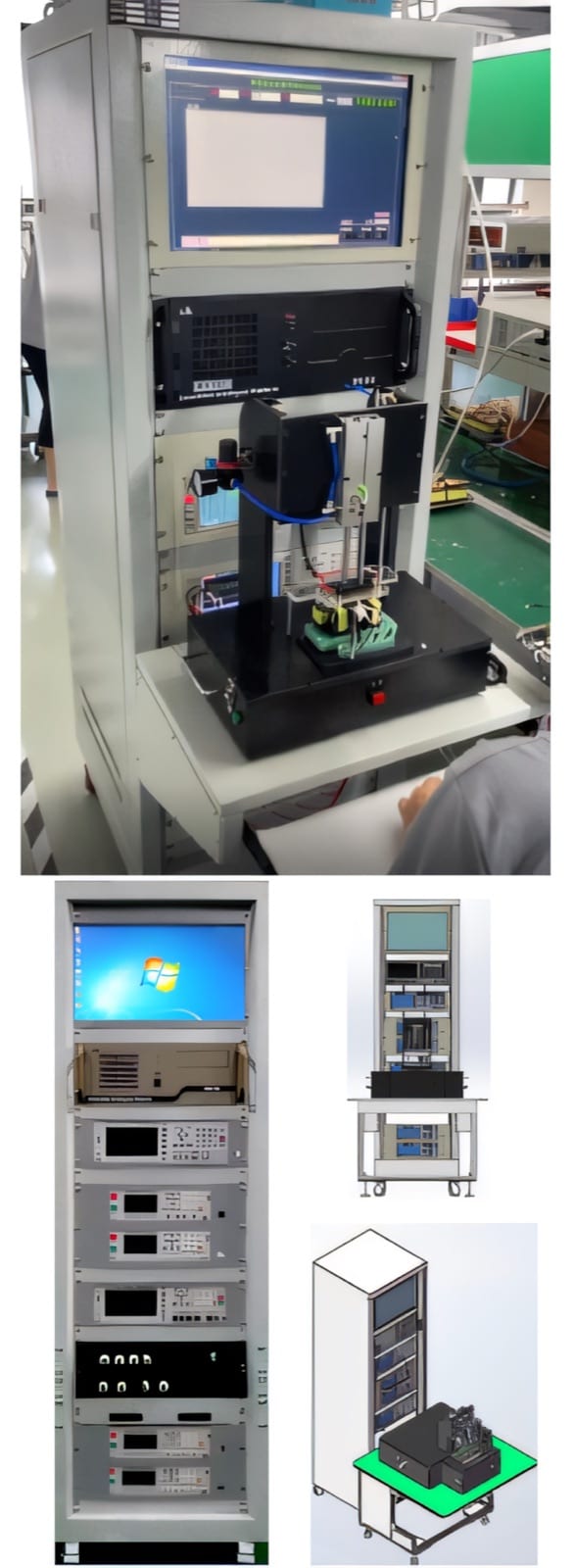
Select parameters from product risk
An LCR instrument can measure several electrical characteristics, but production should focus on parameters that confirm the winding and assembly. Inductance, winding resistance, continuity, quality factor or another value may be useful depending on the product design and customer requirement.
State frequency, test level, connection method, fixture compensation and temperature condition with every limit. The same component can produce different readings under different test conditions, so copying a numerical tolerance without its method creates false comparisons.
Protect measurement integrity at production speed
Fixture contact is often the largest practical source of variation. Use stable datums, suitable probe force and short, controlled connections. Keep test cables and fixtures away from moving power wiring where interference can affect sensitive measurements.
Compensation or zeroing routines should be tied to the actual fixture state. Define when they are performed, who can approve them and how the station is checked with reference components. An automatic pass result is only trustworthy when the measurement path remains under control.
- Defined frequency and test signal
- Fixture compensation procedure
- Reference-component checks
- Temperature and stabilization rules
Fit testing into the line takt
Calculate test time from part handling, contact, settling, measurement, decision and unloading. If one measurement is slow, parallel fixtures or a split test strategy may be better than reducing settling until results become unstable.
Test as early as practical after the operations that create the relevant failure. Continuity after winding can prevent value being added to an open coil, while final electrical limits may belong after core assembly, soldering or cure. The line should carry pass status between stations.
Validate with borderline and failed components
A group of good parts proves repeatability but not detection. Include samples that represent opens, shorts, wrong turns, poor contacts and values near the approved limits. Confirm reject routing and the behaviour after a test interruption or fixture fault.
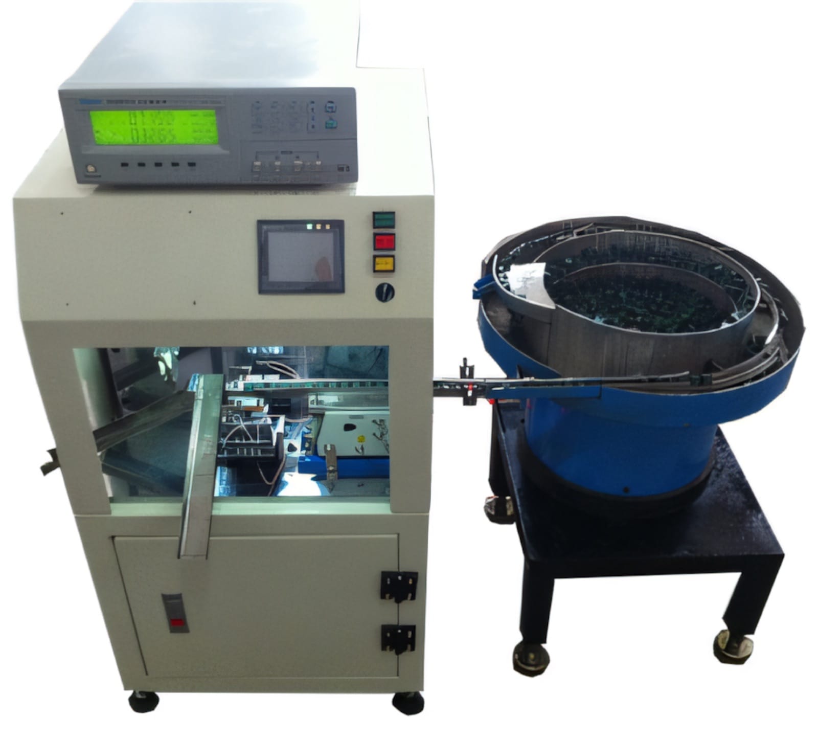
PME automatic inductor, transformer and combined testing systems can integrate LCR-related measurements with feeding and pass/fail separation. The final station should be specified around the approved test plan, target cycle and traceability requirement.
Relevant machinery for this process
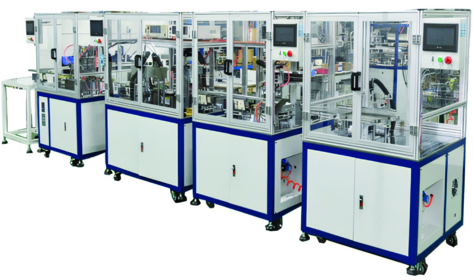
Explore PME equipment that can support the operations discussed in this guide. Final machine selection should be confirmed against your component, materials and target output.
Plan the next step
Discuss your component and production target with PME.
Share a drawing, sample, current process and expected output. We can help map the right machines and level of integration.