
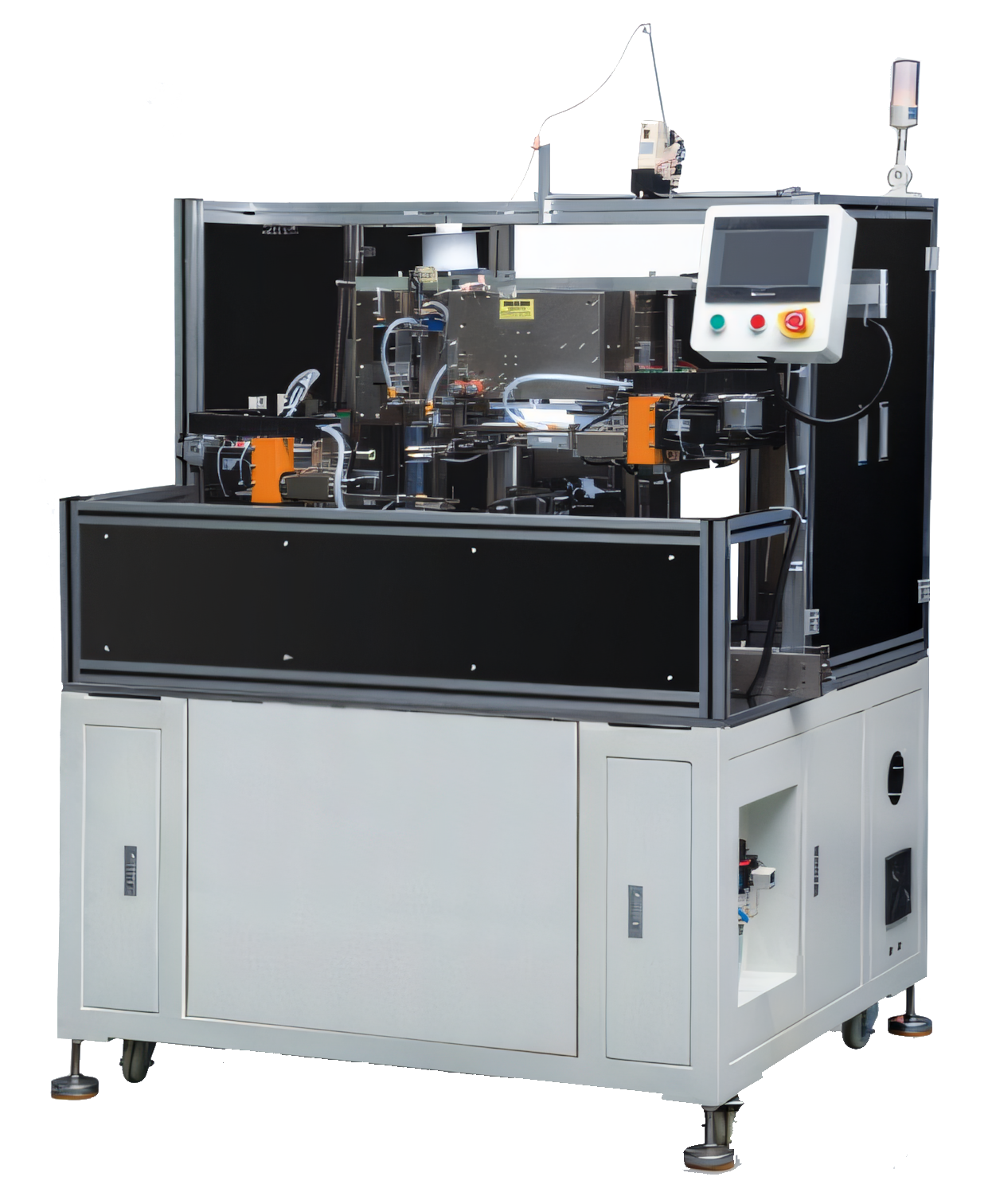
Start with the product and process—not the machine
Inductor automation begins with a clear definition of the part family. Record the core or bobbin geometry, wire diameter, number of turns, winding direction, terminal style, insulation requirements, soldering method and electrical limits. A machine can only repeat a process that has first been made explicit.
Map the existing manual route from incoming material to packed product. Measure cycle time, queue time, rework, operator touches and the points where quality depends on individual skill. This shows where automation will create the most useful stability.
- Part variants and expected production mix
- Target output per shift and acceptable changeover time
- Critical dimensions, tension limits and electrical criteria
- Material replenishment and finished-part handling
Define the automated manufacturing sequence
A typical inductor process may include core or bobbin feeding, wire preparation, winding, termination, taping, soldering, visual inspection and electrical testing. Not every product needs every stage, and the order can change with the component design.
The goal is to create a stable sequence with clear inputs and outputs at each station. A station should know when a part is present, whether the preceding operation passed, and where to send a rejected component.
- Automatic or assisted part loading
- Controlled winding and wire tension
- Terminal connection, soldering or welding
- Electrical test with pass/fail separation
Choose the right level of integration
Automation does not always require one large machine. A manufacturer may begin with a standalone winding machine and add taping, soldering and testing as separate stations. This reduces the first investment and makes each process easier to change.
A connected production line becomes more attractive when volume is stable, the part family is well defined and manual transfer is causing labour, traceability or quality problems. The line can share part handling, recipes, safety controls and production data.
Prove the process before scaling it
Before final approval, run representative materials and samples across the expected operating range. Validate winding quality, solder consistency, test repeatability, changeover, fault recovery and operator access. Include difficult but realistic conditions such as a nearly empty wire spool or a minor part-position variation.
The strongest automation projects are phased around measurable acceptance criteria. Confirm output, first-pass yield, downtime response and training requirements before treating the system as production-ready.
Relevant machinery for this process
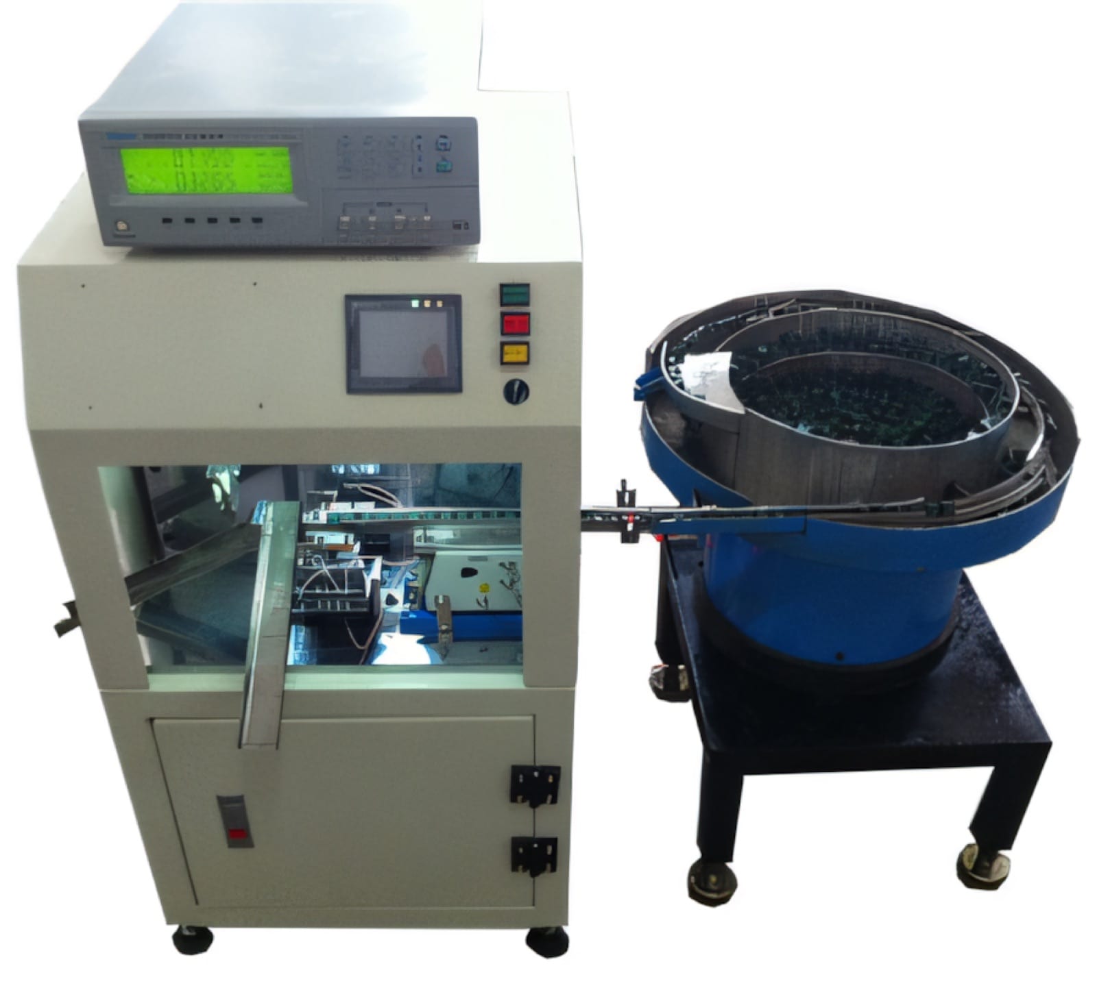
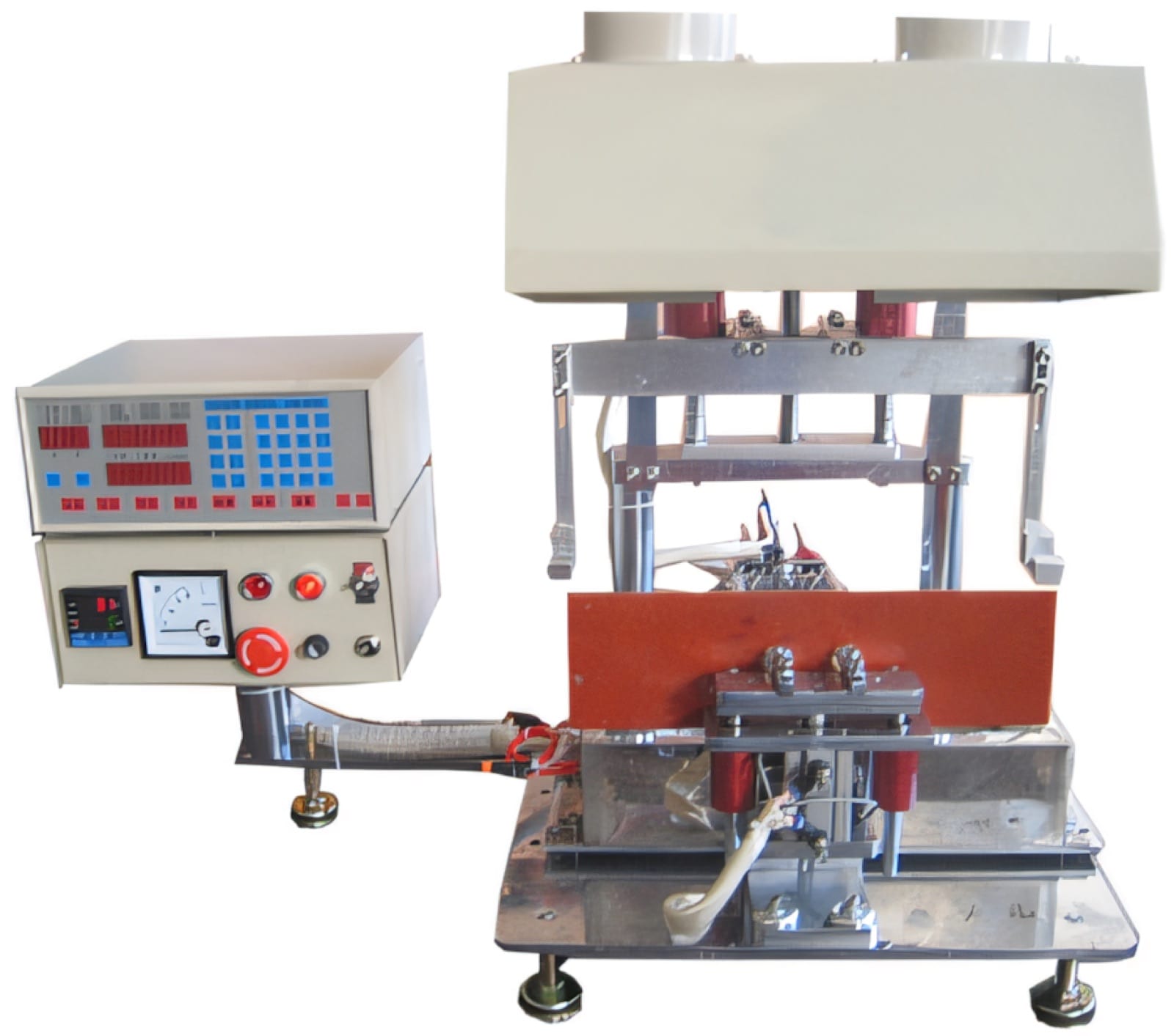
Explore PME equipment that can support the operations discussed in this guide. Final machine selection should be confirmed against your component, materials and target output.
Plan the next step
Discuss your component and production target with PME.
Share a drawing, sample, current process and expected output. We can help map the right machines and level of integration.