
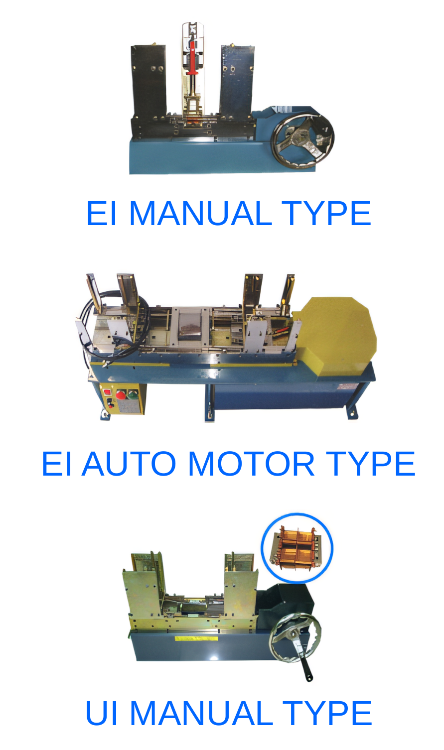
Begin with lamination and bobbin variation
EI and UI core assembly depends on thin laminations arriving flat, correctly oriented and within dimensional tolerance. Burrs, oil, warped pieces and mixed stacks can cause feeding or insertion faults that no motion program can fully correct. Define incoming limits and include production-lot variation in trials.
The bobbin or coil assembly also needs stable datums and enough clearance for the approved stack. Measure the difficult combinations, such as the upper-limit lamination with the lower-limit window, rather than proving the process only with nominal parts.
Design feeding and orientation around the core style
The machine must separate individual plates without lifting a double piece, then present each one in the correct direction. Sensors can confirm presence, but mechanical tooling should prevent an incorrect orientation from reaching the insertion point wherever practical.
Alternate stacking patterns and EI or UI sequences should be explicit in the recipe. If several sizes share one machine, change parts should be keyed, labelled and easy to inspect so setup errors are found before a full stack is assembled.
- Single-plate separation
- Orientation and type verification
- Stack sequence and count
- Change-part identification
Control insertion force and finished stack
Insertion should guide the plate without scraping insulation, bending laminations or damaging the bobbin. Monitor force or motion behaviour where it provides useful fault detection, and define the response to a high-force event. Repeated retries can turn a recoverable misfeed into product damage.
After assembly, confirm stack height, plate count, seating and any clamping or taping requirement. Electrical testing may be needed after core completion because gaps, incorrect material or assembly damage can influence the finished transformer.
Evaluate automation using good assembled cores
Cycle time should count normal replenishment, rejected plates and recovery, not only uninterrupted insertion. Measure good assemblies per hour, operator activity, changeover and scrap. A slightly slower system with stable separation can outperform a fast machine that stops frequently.
PME EI/UI core plate insertion equipment can be configured around the lamination, bobbin and stacking sequence. Samples, drawings and a defined acceptance plan are essential for proving feeding, insertion quality and compatibility with later taping or testing.
Relevant machinery for this process
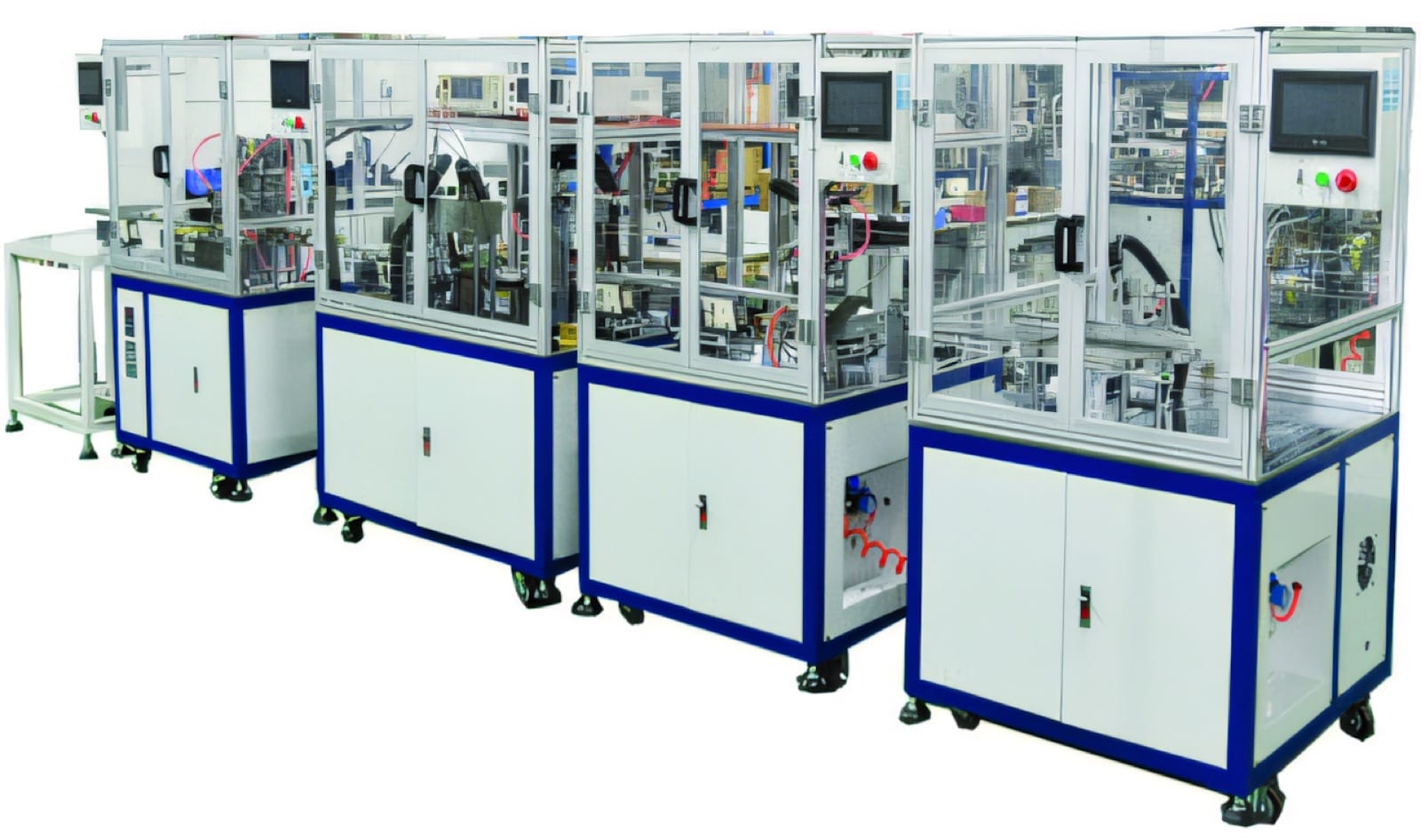
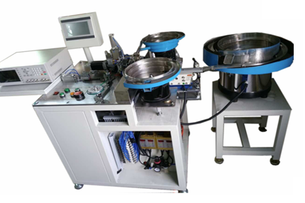
Explore PME equipment that can support the operations discussed in this guide. Final machine selection should be confirmed against your component, materials and target output.
Plan the next step
Discuss your component and production target with PME.
Share a drawing, sample, current process and expected output. We can help map the right machines and level of integration.