
Treat tape appearance as process evidence
Wrinkles, loose layers and uneven overlap indicate that material delivery and component motion are not working together. The visible defect may come from tape tension, misalignment, changing roll drag, part runout, tooling pressure or an incorrect recipe.
Mark the defect location relative to the start, corners, leads and finish. A wrinkle that repeats at the same rotation points toward geometry or motion; a problem that grows through the roll suggests unwind or material variation. This pattern is more useful than immediately increasing tension.
Control material and unwind behaviour
Tape width, backing, adhesive, liner and roll quality affect the process. Store and condition material according to its specification, and prevent damaged roll edges from entering production. Confirm that replacement rolls match the approved part number and width.
Unwind drag changes as roll diameter falls unless the machine compensates for it. Guides and rollers should turn freely and keep the web centred. Adhesive buildup can pull the tape sideways or create intermittent tension, so cleaning frequency belongs in the setup standard.
- Approved tape and width
- Roll-edge and splice inspection
- Clean, aligned guides
- Stable tension across roll diameter
Balance overlap, speed and component motion
Overlap comes from the relationship between rotational speed and tape traverse. If either changes without the other, coverage changes. Store both in the recipe and verify actual overlap on the first piece rather than relying only on programmed values.
Corners, variable diameters and lead exits may need controlled speed changes or dedicated tooling. Excess tension can distort a bobbin or stretch tape; insufficient tension can leave loose layers. Tune within the product and material limits, then test insulation or mechanical performance as required.
Make changeover and inspection repeatable
Use labelled guides, stops and tooling for each product family. The setup sheet should define tape path, tension setting, start point, overlap, number of layers and finish method. First-piece approval should include hidden or underside areas that are easy to miss during a quick visual check.
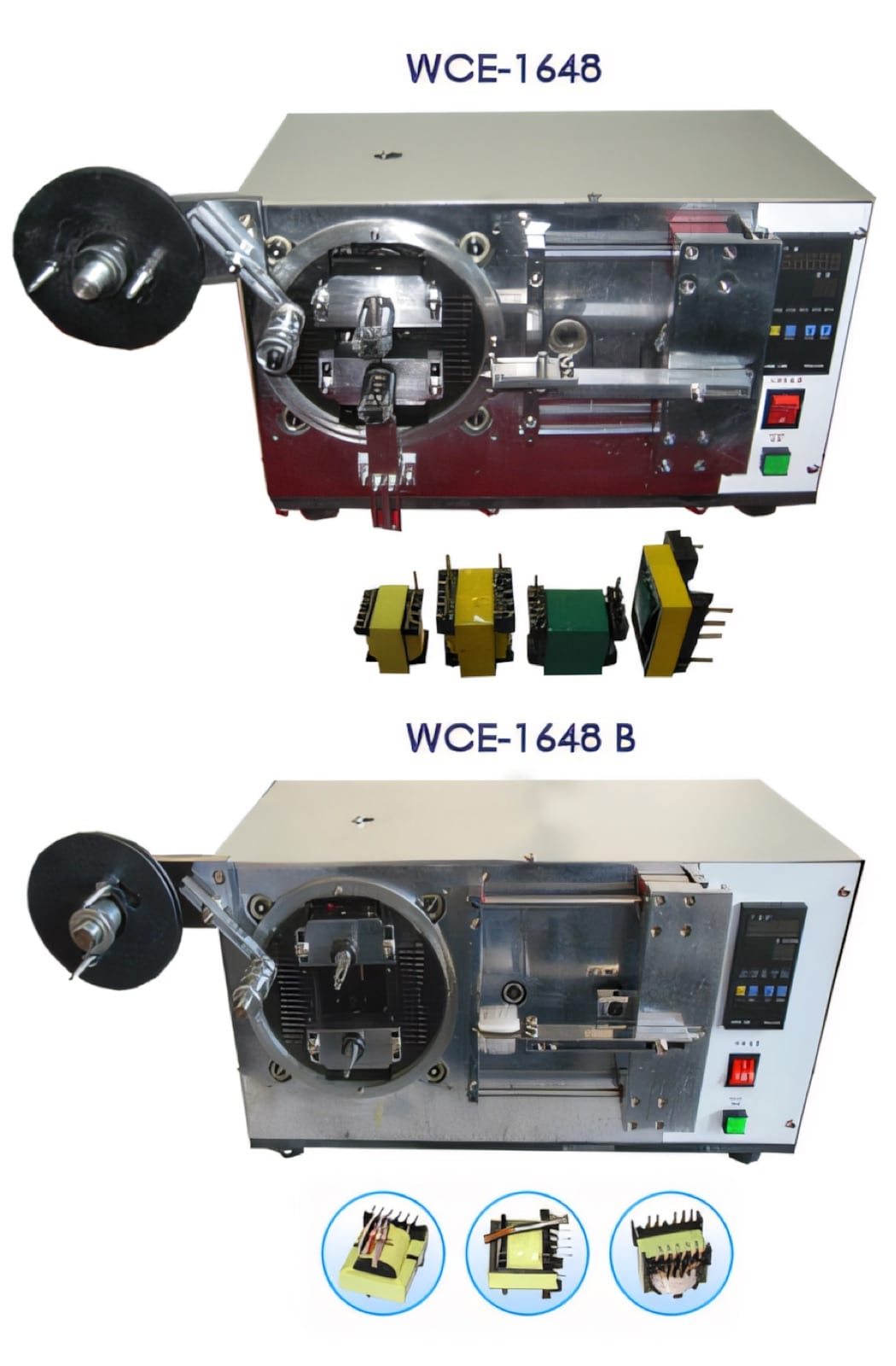
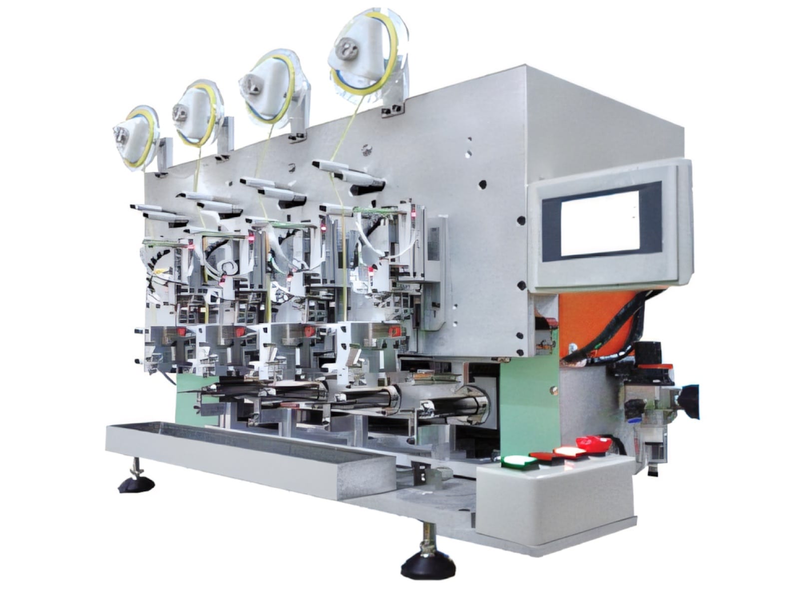
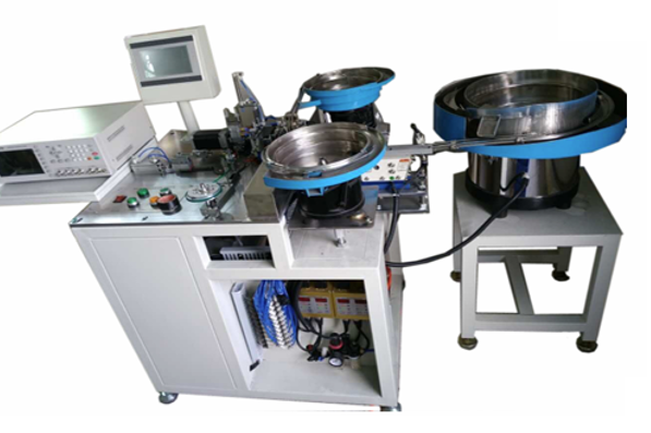
PME offers automatic coil and core taping machines, PLC-controlled configurations and integrated core-assembly systems. A trial with production tape and the full component range can establish stable coverage, cycle time and the maintenance points that protect quality.
Relevant machinery for this process
Explore PME equipment that can support the operations discussed in this guide. Final machine selection should be confirmed against your component, materials and target output.
Plan the next step
Discuss your component and production target with PME.
Share a drawing, sample, current process and expected output. We can help map the right machines and level of integration.